the12volt.com spacer
icon

rf remote lock/unlock universal


Post ReplyPost New Topic
< Prev Topic Next Topic >
axel87 
Member - Posts: 13
Member spacespace
Joined: August 25, 2012
Location: North Dakota, United States
Posted: February 26, 2014 at 6:26 AM / IP Logged  
Installed remote lock actuators in my truck recently, all is working great.
Then I thought why not throw in an RF kit for remote locks.
I installed the actuators with this relay schematic below-
https://www.the12volt.com/relays/relaydiagram49.html
I then connected the RF kit to the motor leg outputs.
Heres the kit I installed-
http://www./itm/370812147602?var=640085943999&ssPageName=STRK:MEWNX:IT&_trksid=p3984.m1439.l2649
I can hear the relays clicking in the module, but they will not activate the actuators.
My question is, is my choice of a relay diagram correct/compatible with this units operation?
I notice the unit has a one leg operation for lock unlock, were as my switch has 2 legs.
Thanks guys!
axel87 
Member - Posts: 13
Member spacespace
Joined: August 25, 2012
Location: North Dakota, United States
Posted: February 26, 2014 at 6:28 AM / IP Logged  
I should add I ordered the 2 Channel self locking.
Added 12v power and gnd to unit, spliced into the two output legs of the switch relays.
freqsounds 
Copper - Posts: 289
Copper spacespace
Joined: October 17, 2008
Location: Virginia, United States
Posted: February 26, 2014 at 8:19 AM / IP Logged  
Can you send the make/model of the RF kit? It messed up the URL.
Is the output on the RF kit a (-) output? Most of them are. If so, you'll have to change the design of the relays a little bit.
No question is stupid or not worth asking. You were once a noob, right? :)
axel87 
Member - Posts: 13
Member spacespace
Joined: August 25, 2012
Location: North Dakota, United States
Posted: February 26, 2014 at 4:54 PM / IP Logged  
http://www./itm/370812147602?var=640085943999&ssPageName=STRK:MEWNX:IT&_trksid=p3984.m1439.l2649
Try that link- dunno what happened with my original post.
Its a no name model. A Cheap kit, but hopefully itll work.
Still working with supplier, if I need to I am open to purchasing other quality kits, if you have recommendations.
Thanks again!
axel87 
Member - Posts: 13
Member spacespace
Joined: August 25, 2012
Location: North Dakota, United States
Posted: February 26, 2014 at 8:39 PM / IP Logged  
axel87 
Member - Posts: 13
Member spacespace
Joined: August 25, 2012
Location: North Dakota, United States
Posted: February 26, 2014 at 8:41 PM / IP Logged  
well wth... I dont understand how this is not working.
Copy paste link. Why does this keep screwing with me?
If anyone has the patience to deal with this, I would appreciate it.
Ebay
Search
DC 12V RF Wireless Remote Control Switch Receiver+Transmitter 2 CH /4 CH
This is the kit.
Sorry I cant get link to work
axel87 
Member - Posts: 13
Member spacespace
Joined: August 25, 2012
Location: North Dakota, United States
Posted: March 01, 2014 at 1:20 PM / IP Logged  
Would this be the relay wiring that I will need to implement instead?
https://www.the12volt.com/relays/relaydiagram4.html
Thanks for any help guys!
freqsounds 
Copper - Posts: 289
Copper spacespace
Joined: October 17, 2008
Location: Virginia, United States
Posted: March 01, 2014 at 1:31 PM / IP Logged  
Alright, I got the diagram open. What configuration are you using? Is it the 2CH receiver+remote (self-locking)?
No question is stupid or not worth asking. You were once a noob, right? :)
axel87 
Member - Posts: 13
Member spacespace
Joined: August 25, 2012
Location: North Dakota, United States
Posted: March 01, 2014 at 6:28 PM / IP Logged  
Thank you for your time!
Correct, 2 channel self locking
I have the actuators wiring to seperate relays with a switch under this configuration-
https://www.the12volt.com/relays/relaydiagram49.html
This part is working correctly. I thought I could just hook up the output of the module to the actuator legs.
No go though :(
Any ideas?
Thanks
freqsounds 
Copper - Posts: 289
Copper spacespace
Joined: October 17, 2008
Location: Virginia, United States
Posted: March 01, 2014 at 7:36 PM / IP Logged  
rf remote lock/unlock universal -- posted image.
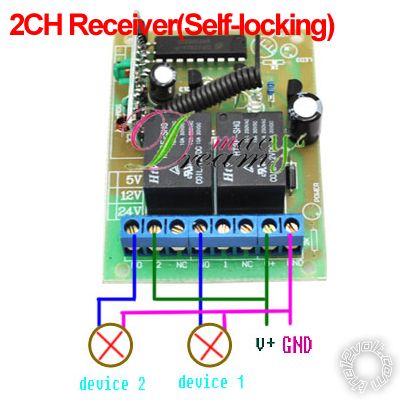
Starting from left to right, wire up as follows:
TERM1 - spliced into pin 86 from relay 1
TERM2 - +12V Constant
TERM3
TERM4 - spliced into pin 85 from relay 2
TERM5
TERM6
TERM7 - +12V Constant
TERM8 - Ground
The relays I'm speaking of are your existing relays that currently control the locks with a switch.
Now, if your locks operate backwards (i.e. unlock locks and lock unlocks) switch TERM1 and TERM4.
No question is stupid or not worth asking. You were once a noob, right? :)
Page of 2

  Printable version Printable version Post ReplyPost New Topic
You cannot post new topics in this forum
You cannot reply to topics in this forum
You cannot delete your posts in this forum
You cannot edit your posts in this forum
You cannot create polls in this forum
You cannot vote in polls in this forum

  •  
Search the12volt.com
Follow the12volt.com Follow the12volt.com on Facebook
Thursday, April 25, 2024 • Copyright © 1999-2024 the12volt.com, All Rights Reserved Privacy Policy & Use of Cookies
Disclaimer: *All information on this site ( the12volt.com ) is provided "as is" without any warranty of any kind, either expressed or implied, including but not limited to fitness for a particular use. Any user assumes the entire risk as to the accuracy and use of this information. Please verify all wire colors and diagrams before applying any information.

Secured by Sectigo
the12volt.com spacer
Support the12volt.com
Top
the12volt.com spacer