the12volt.com spacer
icon

Viper 5706v, 2010 Hyundai Elantra


Post ReplyPost New Topic
< Prev Topic Next Topic >
wissam1981 
Copper - Posts: 116
Copper spacespace
Joined: July 24, 2014
Location: Florida, United States
Posted: September 04, 2014 at 1:27 PM / IP Logged  
Final Confirmation Please
H1/1   Red (12v) Constant Input
H3/2   RED / BLACK (+) FUSED 12V ACCESSORY/STARTER INPUT
H3/5   RED (+) FUSED 12V IGNITION 1 INPUT
H3/10 PINK (+) IGNITION 1 INPUT/OUTPUT
H3/9   RED / WHITE (+) FUSED 12V IGNITION 2 / FLEX RELAY INPUT 87
All the above to    12 Volts red to black (40A) + ignition switch, white 6 pin plug, pin 5
H1/2    Black (-) CHASSIS GROUND —— Vehicle ground
H1/3    (+) SIREN OUTPUT     —— Siren
H1/5    PARKING LIGHT OUTPUT ——— ( Parking Lights (+) pink (L), BROWN / orange (R) + dash fuse box, rear, white 30 pin plug (F), pins 22 and 6 ) OR ( Parking Lights (-) orange - headlight switch, white 14 pin plug, pin 8 )
H2/3 RED / White (-) 200mA TRUNK RELEASE OUTPUT   —— ????????
H2/4 BLACK/ Yallow (-) 200mA DOME LIGHT OUTPUT —— Dome Supervision yellow - driver kick, gray 39 pin plug, pin 14
H2/9 Gray (-) HOOD PIN INPUT (NC OR NO) —— Hood Pin in Viper
H2/10 (-) TRUNK PIN/INSTANT TRIGGER INPUT (N/C OR N/O)   —— Trunk/Hatch Pin GREEN/ black - driver kick, gray 39 pin plug, pin 11
H2/12   VIOLET/WHITE* TACHOMETER INPUT   —— Tachometer blue/red (front of plug) to red (back of plug) ac passenger kick, gray 39 pin plug, pin 5
H2/13   BLACK/ WHITE**   (-) NEUTRAL SAFETY /PARKING BRAKE INPUT    ———— to Vehicle Ground
H2/15   Green (-) DOOR INPUT ——— ????????
H2/20 H2/20 To ( Brake Wire black + driver kick, gray 39 pin plug, pin 34 ) OR ( Parking Brake blue - dash fuse box, rear, white 20 pin plug (C), pin 8 )
H3/6 GREEN (+) STARTER INPUT (KEY SIDE OF THE STARTER KILL) —— Starter BLACK / YELLOW to white + ignition switch, ( To Key side )
H3/7   VIOLET (+) STARTER OUTPUT (CAR SIDE OF THE STARTER KILL) —— Starter BLACK / YELLOW to white + ignition switch, ( to Car Side )
H3/8   ORANGE (+) ACCESSORY OUTPUT —— Accessory white to orange + ignition switch, white 6 pin plug, pin 3
howie ll 
Pot Metal - Posts: 16,466
Pot Metal spacespace
Joined: January 09, 2007
Location: United Kingdom
Posted: September 04, 2014 at 2:28 PM / IP Logged  
Do nothing!
You are about as wrong as it's possible to be.
I'll get back to you with (lots of) corrections tomorrow.
howie ll 
Pot Metal - Posts: 16,466
Pot Metal spacespace
Joined: January 09, 2007
Location: United Kingdom
Posted: September 04, 2014 at 5:02 PM / IP Logged  
H1/1   Red (12v) Constant Input
H3/2   RED / BLACK (+) FUSED 12V ACCESSORY/STARTER INPUT
H3/5   RED (+) FUSED 12V IGNITION 1 INPUT
H3/10 PINK (+) IGNITION 1 INPUT/OUTPUT
H3/9   RED / WHITE (+) FUSED 12V IGNITION 2 / FLEX RELAY INPUT 87
All the above to    12 Volts red to black (40A) + ignition switch, white 6 pin plug, pin 5
NO Pink to ign, if 2nd ign, pink/white to second ignition.
H1/5    PARKING LIGHT OUTPUT You will want left and right indicators, at steering column loom.
H2/3 RED / White (-) 200mA TRUNK RELEASE OUTPUT   —— ????
Is there an electric trunk release? You can look and refer to the instructions, I told you so many times where they are I'm giving up.
H2/4 BLACK / YELLOW (-) 200mA DOME LIGHT OUTPUT Again! I told you not to bother.
H2/15   Green (-) DOOR INPUT ——— ??? Again repeating the same questions for which either the list I posted or previous answers should tell you.
wissam1981 
Copper - Posts: 116
Copper spacespace
Joined: July 24, 2014
Location: Florida, United States
Posted: September 05, 2014 at 3:21 PM / IP Logged  
1- what the step after hooking all wires
2- i don't understand the ( learning the Tach ), should i do there steps ?
3- regarding the remote, should i pair it or its already paired to the system ?
howie ll 
Pot Metal - Posts: 16,466
Pot Metal spacespace
Joined: January 09, 2007
Location: United Kingdom
Posted: September 06, 2014 at 2:35 AM / IP Logged  
1) See 2 and 3
2) Read the programming instructions H2/15 GREEN must be connected to a door pin (see fitting guide) or GROUNDED.
3) Should already be paired try an on off first with each remote once the wiring is completed then go on to program tach.
wissam1981 
Copper - Posts: 116
Copper spacespace
Joined: July 24, 2014
Location: Florida, United States
Posted: September 06, 2014 at 3:18 AM / IP Logged  
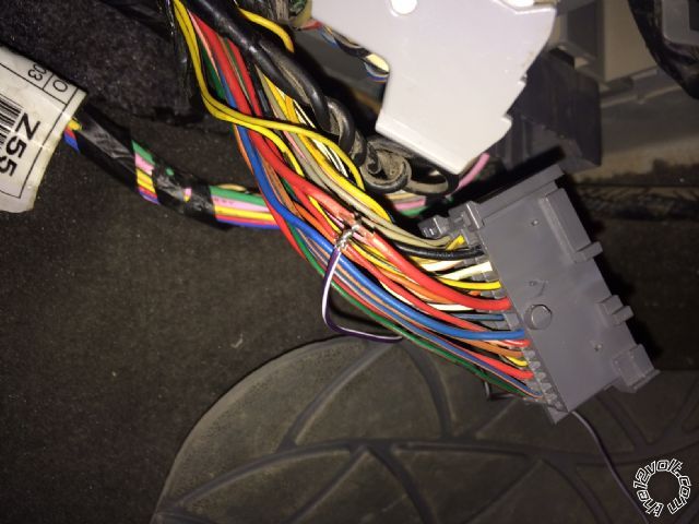
please check this image ( Tachometer ) Connecting, is this image correct ?
Viper 5706v, 2010 Hyundai Elantra - Page 12 -- posted image.
howie ll 
Pot Metal - Posts: 16,466
Pot Metal spacespace
Joined: January 09, 2007
Location: United Kingdom
Posted: September 06, 2014 at 3:25 AM / IP Logged  
Yes it's correct although you might need to place more solder on that joint. It must sink into both wires and be shiny.
wissam1981 
Copper - Posts: 116
Copper spacespace
Joined: July 24, 2014
Location: Florida, United States
Posted: September 06, 2014 at 3:37 AM / IP Logged  
i am having trouble finding the ( parking light ) on my vehicle, please help
howie ll 
Pot Metal - Posts: 16,466
Pot Metal spacespace
Joined: January 09, 2007
Location: United Kingdom
Posted: September 06, 2014 at 3:43 AM / IP Logged  
You need to go to the direction indicators (turn signal)left and right as in the instructions. Place internal fuse in the (+) position then split the white wire via 2 X 1N5404 diodes (any electronics store, repair facility etc.) bands away from 5706 to each wire.
wissam1981 
Copper - Posts: 116
Copper spacespace
Joined: July 24, 2014
Location: Florida, United States
Posted: September 06, 2014 at 3:50 AM / IP Logged  
is it required for programming ? if not, can i connect it later ?
Page of 22

  Printable version Printable version Post ReplyPost New Topic
You cannot post new topics in this forum
You cannot reply to topics in this forum
You cannot delete your posts in this forum
You cannot edit your posts in this forum
You cannot create polls in this forum
You cannot vote in polls in this forum

  •  
Search the12volt.com
Follow the12volt.com Follow the12volt.com on Facebook
Saturday, June 15, 2024 • Copyright © 1999-2024 the12volt.com, All Rights Reserved Privacy Policy & Use of Cookies
Disclaimer: *All information on this site ( the12volt.com ) is provided "as is" without any warranty of any kind, either expressed or implied, including but not limited to fitness for a particular use. Any user assumes the entire risk as to the accuracy and use of this information. Please verify all wire colors and diagrams before applying any information.

Secured by Sectigo
the12volt.com spacer
Support the12volt.com
Top
the12volt.com spacer