the12volt.com spacer
icon

Viper 5706v, 2010 Hyundai Elantra


Post ReplyPost New Topic
< Prev Topic Next Topic >
catback 
Silver - Posts: 703
Silver spacespace
Joined: August 13, 2002
Location: Canada
Posted: September 08, 2014 at 9:20 AM / IP Logged  
wissam1981 wrote:
2- i start my vehicle with R/S, when i pressed the brake the vehicle shutdown, is this normal.
Yes it is normal. Insert key and turn to ON/RUN and then press on brake if you wish to drive car.
wissam1981 
Copper - Posts: 116
Copper spacespace
Joined: July 24, 2014
Location: Florida, United States
Posted: September 08, 2014 at 1:00 PM / IP Logged  
catback wrote:
wissam1981 wrote:
2- i start my vehicle with R/S, when i pressed the brake the vehicle shutdown, is this normal.
Yes it is normal. Insert key and turn to ON/RUN and then press on brake if you wish to drive car.
okay, i get it now thanks
now i have last three problems.
1- problem with ( lock and unlock wires ), when i test the 3 pin connecter( By tester light) , its (+) must be (-) . Why?
2- when i try to connect the parking wires (white) in 6-pin connector and trying to start the vehicle by remote, it's started for about 15 sec. and shutdown for it self, ( this process take 3 times ) and finally shutdown. but when i disconnect this wire the vehicle operate normally.
3- you remember that i told you about AC not working, i tried your advice by arming the vehicle and leave it and starting it ( but i didn't get how to set levels as you said ), same issue ( AC not working), so i tried to connect ignition wire (pink) to both wires ( ignition 1 + 2) in ignition switch, it's operate normally and the vehicle AC worked fine, is it save what i did or not ?
howie ll 
Pot Metal - Posts: 16,466
Pot Metal spacespace
Joined: January 09, 2007
Location: United Kingdom
Posted: September 08, 2014 at 4:36 PM / IP Logged  
Just connect the lock/unblock wires as per the instructions.
But you told me there was only one ignition!
Test the two wires in the ignition loom that flash on and off when you turn on the ignition and move the direction indicator left and right.
Make sure you've set the unit's fuse to POS and split that white wire via 2 X 1N5404 diodes.
You told me there was only one ignition wire, now you're telling me there are two. Use your pink/white for the second ignition,do not join both ignition wires to your pink it will cause very expensive electrical overload problems later on.
wissam1981 
Copper - Posts: 116
Copper spacespace
Joined: July 24, 2014
Location: Florida, United States
Posted: September 08, 2014 at 5:36 PM / IP Logged  
i put the PINK/WHITE to ignition 2, and RED / WHITE to 12v source, same issue ( AC not working), do i need a relay on ignition 2 ?
( Just connect the lock/unblock wires as per the instructions), what the instructions says?
( Make sure you've set the unit's fuse to POS and split that white wire via 2 X 1N5404 diodes) i did that with same problem
howie ll 
Pot Metal - Posts: 16,466
Pot Metal spacespace
Joined: January 09, 2007
Location: United Kingdom
Posted: September 08, 2014 at 5:39 PM / IP Logged  
Then recheck your wiring.
wissam1981 
Copper - Posts: 116
Copper spacespace
Joined: July 24, 2014
Location: Florida, United States
Posted: September 08, 2014 at 6:11 PM / IP Logged  
about lock/unlock
Door lock 3 pin connecter
1- blue (-) 500ma unlock output ------- Power Unlock yellow - driver kick, gray 39 pin plug, pin 39
2- Green (-) 500mA LOCK OUTPUT ------- Power Lock green - driver kick, gray 39 pin plug, pin 25
Right?
howie ll 
Pot Metal - Posts: 16,466
Pot Metal spacespace
Joined: January 09, 2007
Location: United Kingdom
Posted: September 09, 2014 at 1:27 AM / IP Logged  
Yes.
wissam1981 
Copper - Posts: 116
Copper spacespace
Joined: July 24, 2014
Location: Florida, United States
Posted: September 09, 2014 at 4:58 PM / IP Logged  
wissam1981 wrote:
about lock/unlock
Door lock 3 pin connecter
1- blue (-) 500ma unlock output ------- Power Unlock yellow - driver kick, gray 39 pin plug, pin 39
2- Green (-) 500mA LOCK OUTPUT ------- Power Lock green - driver kick, gray 39 pin plug, pin 25
Right?
1- i connect it as above and didn't work, any ideas?
is there any programming steps that i should do first ?
2- i am still couldn't do the ( learning Tach ), i follow the steps in the manual, nothing happened, why?
3- i realised that there is feature in Menu 3, option 2 ( tachometer, and virtual Tach )
i am still until now not understanding the benefit of tachometer, and the learning Tach? please can you give me some information about it ?
wissam1981 
Copper - Posts: 116
Copper spacespace
Joined: July 24, 2014
Location: Florida, United States
Posted: September 09, 2014 at 5:23 PM / IP Logged  
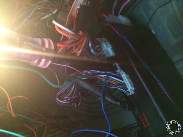
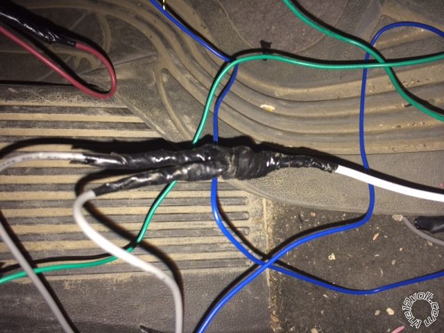
please check out these images
1- this is 3 pin harness, as you see the blue wire have power all the time, is this normal ?
it says in the manual (-), i can't understand it
Viper 5706v, 2010 Hyundai Elantra - Page 15 -- posted image.
2- i am facing until now the shutdown problem ( when i connect the parking light wire ), so i disconnect it ( for now ) until i figure out whats happening, any ideas ?
P. S. i realise when i connect the parking light wire and start the vehicle, the diodes become overheat. is this normal ?
thanks in advance
Viper 5706v, 2010 Hyundai Elantra - Page 15 -- posted image.
wissam1981 
Copper - Posts: 116
Copper spacespace
Joined: July 24, 2014
Location: Florida, United States
Posted: September 10, 2014 at 12:38 PM / IP Logged  
Howie, where are you man, I need you
Page of 22

  Printable version Printable version Post ReplyPost New Topic
You cannot post new topics in this forum
You cannot reply to topics in this forum
You cannot delete your posts in this forum
You cannot edit your posts in this forum
You cannot create polls in this forum
You cannot vote in polls in this forum

  •  
Search the12volt.com
Follow the12volt.com Follow the12volt.com on Facebook
Sunday, June 2, 2024 • Copyright © 1999-2024 the12volt.com, All Rights Reserved Privacy Policy & Use of Cookies
Disclaimer: *All information on this site ( the12volt.com ) is provided "as is" without any warranty of any kind, either expressed or implied, including but not limited to fitness for a particular use. Any user assumes the entire risk as to the accuracy and use of this information. Please verify all wire colors and diagrams before applying any information.

Secured by Sectigo
the12volt.com spacer
Support the12volt.com
Top
the12volt.com spacer