the12volt.com spacer
icon

2013-2014 Accord Remote Starter Install Pictorial


Post ReplyPost New Topic
< Prev Topic Next Topic >
kreg357 
Platinum - Posts: 7,804
Platinum spaceThis member has made a donation to the12volt.com. Click here for more info.spaceThis member has been recognized as an authority in Electrical Theory. Click here for more info.spaceThis member has been recognized as an authority in Mobile Security and Convenience. Click here for more info.spacespace
Joined: January 30, 2009
Location: Pennsylvania, United States
Posted: September 13, 2014 at 10:03 AM / IP Logged  

This R/S w/Keyless Entry Pictorial is on the 2013 & 2014 Honda Accord and covers the LX and Sport models that use

the standard key ignition system and is intended for advanced DIY'ers.  It does not cover the Accord's with "Push to
Start" ignition systems.

For this install a Compustar CM6200-s and an ADS AL-CA bypass module flashed with the DL HA6 firmware was used. 

W2W mode connections were made between the CM6200-s and ADS AL-CA.   Semi-finished bench prepped unit : 
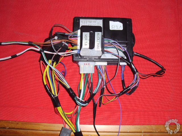
2013-2014 Accord Remote Starter Install Pictorial -- posted image.

The install guides for the available bypass modules are very good and should be used as your primary reference.  As

such, this Pictorial will be slightly redundant but will provide some additional useful photo's and information. 

While you could do this vehicle with the Valet key in a universal "key-in-the-box" style bypass module and hard wire

everything, using a full featured bypass module like the EVO-ALL or the ADS AL-CA ( or OEM offspring ) has many
advantages.  The big negative is the need for the ADS USB or Fortin FlashLink cable to perform the necessary KLON
or DCryptor process.  If you are a DIY'er, please visit the Fortin WEB site (  http://fortin.ca/en/ ) and do some research
before attempting this install.  Due to the additional equipment and WEB site access required, this is really a professional
or very advanced DIY'er install.

In the U.S. market vehicles, the LX and Sport models come with a Factory Alarm.  This is good and bad.  The good

part is the factory hood pin can be used by the R/S system, the bad part is you must incorporate alarm arm and
disarm into the R/S install.  Using a full featured bypass module makes this very easy.  Additionally, Honda turns off
the factory remotes while the engine is running, so a R/S system with keyless entry is highly recommended.

Let's start taking the vehicle apart :

Remove the lower dash panel by pulling it straight away.  There are many plastic clips that hold it in place as shown

in the photo below :
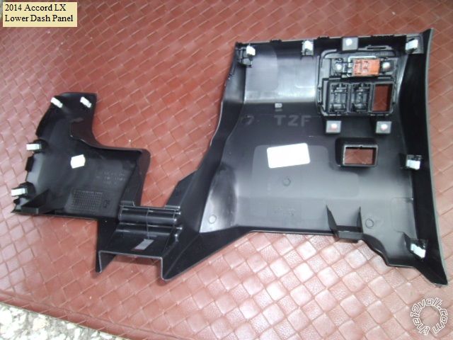
2013-2014 Accord Remote Starter Install Pictorial -- posted image.

Next comes the steering column covers.  Release the upper cover with a non marring tool.   Pictures below :
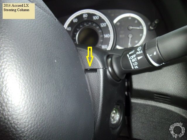
2013-2014 Accord Remote Starter Install Pictorial -- posted image.

Once the upper cover is raised up, you can remove the lower cover retaining screw's at the 10 and 2 o'clock positions.
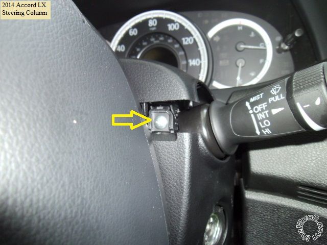
2013-2014 Accord Remote Starter Install Pictorial -- posted image.

Finally, remove the lower cover retaining screw at the underside as indicated in the photo below :
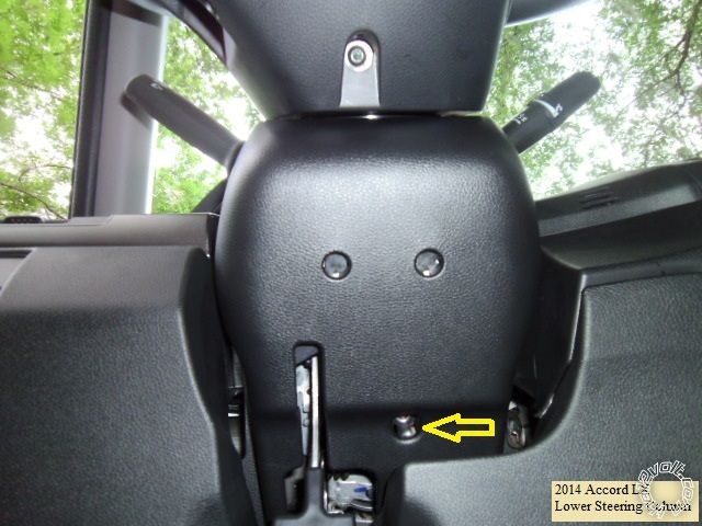
2013-2014 Accord Remote Starter Install Pictorial -- posted image.

You now have access to all the necessary wires.

Here is a picture of the left side of the steering column with the important connectors marked :
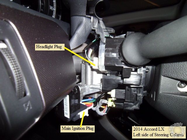
2013-2014 Accord Remote Starter Install Pictorial -- posted image.

This is a close-up of the Parking Light wire ( connector unplugged ) :
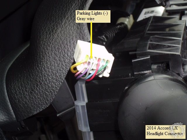
2013-2014 Accord Remote Starter Install Pictorial -- posted image.

Here is a shot of the main ignition harness ( connector unplugged ) :
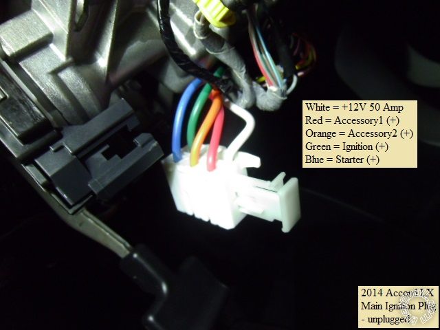
2013-2014 Accord Remote Starter Install Pictorial -- posted image.

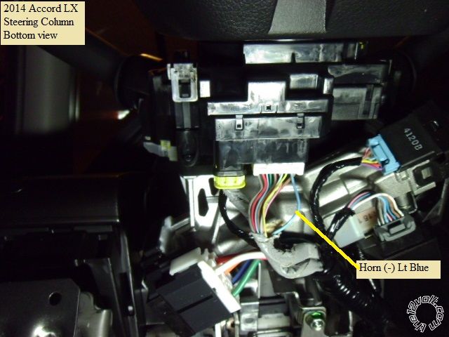
Next is picture of the underside of the steering column with the important connectors marked :
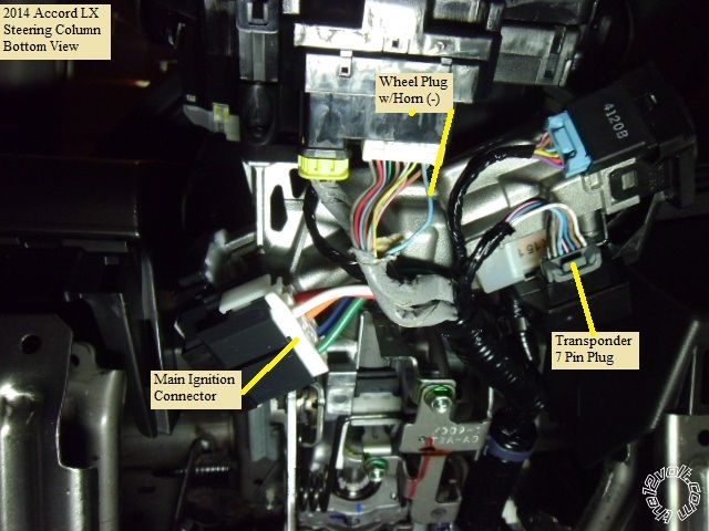
2013-2014 Accord Remote Starter Install Pictorial -- posted image.

Here is the ( optional ) horn wire :

2013-2014 Accord Remote Starter Install Pictorial -- posted image.

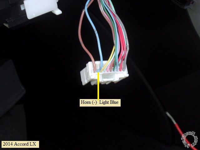
and a close-up of the horn wire :

2013-2014 Accord Remote Starter Install Pictorial -- posted image.

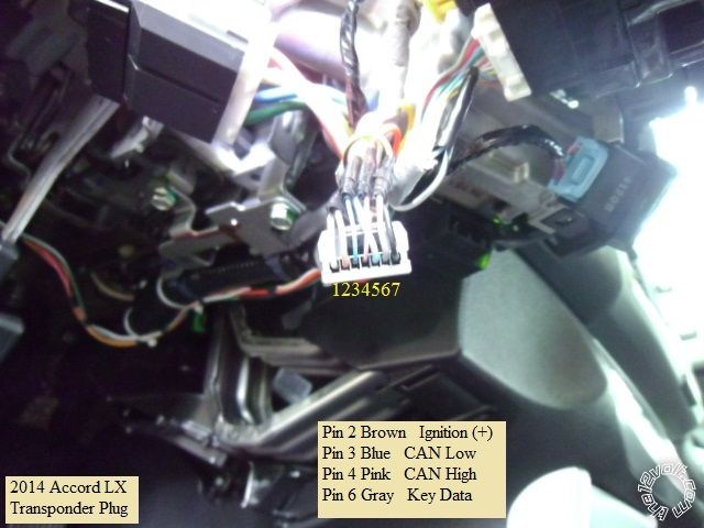
This is a photo of the transponder connector with the wires marked :   ( the bypass install guides have better photos )
2013-2014 Accord Remote Starter Install Pictorial -- posted image.

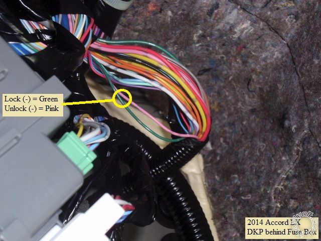
The easiest location to catch the lock wires is in the harness coming from the door, as it goes up the DKP to the

back of the fuse box.  Here is a picture :
2013-2014 Accord Remote Starter Install Pictorial -- posted image.

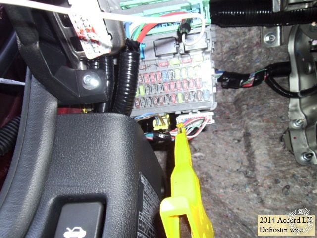
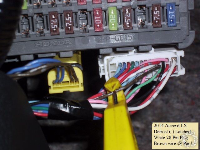
Bonus wires :  The rear defroster can be controlled by the R/S system using a (-) latched output and the wire shown :
2013-2014 Accord Remote Starter Install Pictorial -- posted image.

2013-2014 Accord Remote Starter Install Pictorial -- posted image.

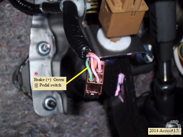
Brake wire :

2013-2014 Accord Remote Starter Install Pictorial -- posted image.

A few notes and tips...

The regular key start Accords do not have "one-touch" starting or built in anti-grind.   Running in Tach mode is

recommended.  Adding anti-grind as an additional cost feature is a nice option.  Due to the tilt / telescopic steering
wheel, making all the ignition connections at the steering column connector is problematic and requires careful
wiring.  Personally, I prefer to make the ignition wire connections at this connector, above the fuse box :
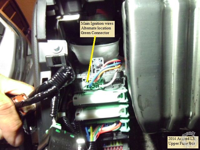
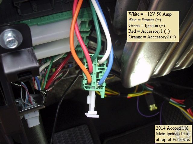
2013-2014 Accord Remote Starter Install Pictorial -- posted image.

2013-2014 Accord Remote Starter Install Pictorial -- posted image.

Be aware that the door locks work differently while the engine is running.  With the engine off, the R/S FOB will act

like the factory FOB and provide progressive unlock.  While the engine is running, the bypass module controls the
lock more directly, using the vehicle lock wires shown above.  With the engine running, an unlock from the R/S FOB
will unlock all doors at once.  

Also, while not mentioned in the bypass install guides, the trunk release from the R/S FOB will not function while the

engine is running ( just like the factory FOB's ).

The drivers door will unlock during a remote start ( to turn off the factory alarm ) so you must set up the R/S system

or bypass module to do a lock after remote start.

There is plenty of room under the dash for module placement.   Good, solid ground screw / bolt locations are abundant.

Using a full featured bypass module eliminates the need to pass any wires through the firewall. 

Note :  All wires should be located and verified with a Digital Multi Meter prior to making your quality soldered connections.  2013-2014 Accord Remote Starter Install Pictorial -- posted image.

Soldering is fun!
smokeman1 
Platinum - Posts: 1,589
Platinum spaceThis member has made a donation to the12volt.com. Click here for more info.spaceThis member has been recognized as an authority in Mobile Security and Convenience. Click here for more info.spacespace
Joined: September 14, 2009
Location: Wisconsin, United States
Posted: September 13, 2014 at 8:31 PM / IP Logged  
Absolutly fabulous. You do great write ups.
When all else fails, Read the Instructions
Support the12volt.com Make a Donation
prdjr165 
Copper - Posts: 293
Copper spacespace
Joined: October 31, 2002
Location: Illinois, United States
Posted: January 03, 2015 at 2:19 PM / IP Logged  
did one today with a Compustar CM5000 and Blade-AL..EASY !This info is spot on !
redknights 
Member - Posts: 13
Member spacespace
Joined: July 24, 2003
Location: United States
Posted: January 29, 2015 at 8:58 AM / IP Logged  
Thanks for the great write up. I have few questions about the install. I'm going to get the Viper 4806 2-way, ADS AL-CA and USB cable for programing. I've a 2014 Accord Sport, STD key, & AT, so I'll follow Type 1 install. If I use the Data Mode cable from RS to iDatalink, do I need to worry about the other Red or dotted line connections from RS to iDatalink? Type 1 didn't mention anything about connecting to the Main harness for 12v, starter, ignition and acc. Do I need to worry about it? I do want a connection to defrost and see the brown wire connection. I also got an account to access iDatalink to flash the firmware, will I also have access for extended programing?
kreg357 
Platinum - Posts: 7,804
Platinum spaceThis member has made a donation to the12volt.com. Click here for more info.spaceThis member has been recognized as an authority in Electrical Theory. Click here for more info.spaceThis member has been recognized as an authority in Mobile Security and Convenience. Click here for more info.spacespace
Joined: January 30, 2009
Location: Pennsylvania, United States
Posted: January 29, 2015 at 11:34 AM / IP Logged  

The Viper 4806 and ADS AL-CA will work well for this install.   Having the ADS USB cable and access will make things easy for

you to do the KLON portion of the bypass programming.  A few things to point out :

1.  If you haven't ordered the ADS AL-CA bypass module, see if you can get a FLCAN module.  It is the same thing but will have

     the proper D2D harness for the connection between the Viper and the bypass module.   If you already have the ADS AL-CA,
     check the package of harness for the D2D cable that has the proper Red connector on one end.  If you don't have it, you can
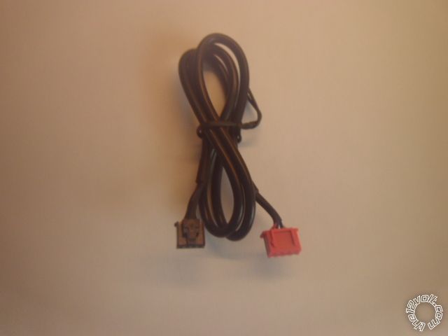
     get one online ( EBay ) for ~ $5, or go in W2W mode like shown in the Pictorial.  The D2D harness looks like this :

2013-2014 Accord Remote Starter Install Pictorial -- posted image.

2.  Connect the USB cable to the PC and the bypass module and sign-on.  The Flash program should recognize the module and

     show you the current firmware and S/N of the bypass module.
3.  Go through the process of selecting the vehicle.  When you get to the point of selecting the Installation Mode, be sure
     to select DBI ( this happens automatically with a FLCAN module ).
4.  On the next page select the DL version of firmware for the flash.  This is the full featured version that does everything, not
     just the transponder bypass.
5.  You can configure features but the defaults are normally satisfactory.  Remember to download the install guide at this point.
     The current guide is #19147 for the ADS AL-CA or #19148 for the FLCAN.

As you mentioned, using the Type 1 install, the D2D harness will handle all the Red dashed lines, so only the necessary Black

solid lines have to be hardwired.  While I don't do D2D, it is interesting that there are differences between the Type 1 diagram
with the ADS AL-CA and the FLCAN.   Anyway follow the appropriate guide.  Follow the Installation Mode Selection process
shown at the top of Page 25 to select DATA ( one blink ) and lock it in.

The bypass module install diagram concerns itself with only the connections that it needs / uses /  controls.  It does not go into

detail about the R/S's connections.  It's generic that way and really can't cover all the different makes and models of R/S systems
it can work with.  For your Viper install you will still need to connect the following wires :
H/1 Red
H/2 Black
H/3 Brown     optional
H/5 White       *set jumper to (-)

Remote Start, 8-pin connector -    All wires except pin 2 are connected to the vehicles ignition harness as shown in Pictorial

1 RED / BLACK (+) 12VDC CONSTANT INPUT White
2 PINK/BLACK (+) FLEX RELAY INPUT 87A    not used
3 PINK/WHITE (+) IGNITION 2 / FLEX RELAY OUTPUT Orange    ** Connect to ACC2 / program Viper to ACC2
4 RED (+) 12VDC CONSTANT INPUT for ignition 1 relay          White
5 VIOLET (+) STARTER OUTPUT        Blue
6 ORANGE (+) ACCESSORY OUTPUT             Red
7 RED / WHITE (+) 12VDC CONSTANT INPUT               White
8 PINK (+) IGNITION 1 INPUT/OUTPUT           Green

Auxiliary/Shutdown Harness 24-pin connector

2 Blue/White        *** use for Defrost and program to Latched output
12 Violet/White    ****Might be required if Viper can't handle Tach via D2D harness
13 BLACK/ White      chassis ground

Good luck with the install!

Soldering is fun!
redknights 
Member - Posts: 13
Member spacespace
Joined: July 24, 2003
Location: United States
Posted: January 29, 2015 at 3:20 PM / IP Logged  
Thanks for the detailed info. I didn't get anything yet, but I'll order the FLCAN, USB cable and Viper within the next few days.
redknights 
Member - Posts: 13
Member spacespace
Joined: July 24, 2003
Location: United States
Posted: January 31, 2015 at 10:39 AM / IP Logged  
One more question about the Viper H/1 Red, I assume that's another 12v connection. Can that also be solder with the white along with the other 3 connections in the ignition harness or should I look for another 12v connection?
kreg357 
Platinum - Posts: 7,804
Platinum spaceThis member has made a donation to the12volt.com. Click here for more info.spaceThis member has been recognized as an authority in Electrical Theory. Click here for more info.spaceThis member has been recognized as an authority in Mobile Security and Convenience. Click here for more info.spacespace
Joined: January 30, 2009
Location: Pennsylvania, United States
Posted: January 31, 2015 at 4:09 PM / IP Logged  
With a basic R/S w/ Keyless entry system ( no alarm functions ), the White +12V wire will handle the current.  If space along the White wire is limited in one area, you could connect two Viper inputs at the White wire above the fuse box and the other two Viper +12V inputs on that same White wire at the steering column.
Soldering is fun!
redknights 
Member - Posts: 13
Member spacespace
Joined: July 24, 2003
Location: United States
Posted: February 02, 2015 at 10:30 AM / IP Logged  
A few more questions. I ended up ordering the Viper 4706v so it should be here at the end of the week. Do I also need to get the 998T Bitwriter to program the Viper? Also looking at Type 1 install of the FLCAN. I'm using D2D but there are still a few W2W that I need in their diagram. I need the wire color from the Viper for the E-Brake and Trunk Status.
Viper Aux Harness     FLCAN
12 Violet/White   to PURPLE / White (Tach)
???(20 Brown)     to Green (E-Brake Status)
???(3 RED / White) to Yellow/Red (Trunk Status)
kreg357 
Platinum - Posts: 7,804
Platinum spaceThis member has made a donation to the12volt.com. Click here for more info.spaceThis member has been recognized as an authority in Electrical Theory. Click here for more info.spaceThis member has been recognized as an authority in Mobile Security and Convenience. Click here for more info.spacespace
Joined: January 30, 2009
Location: Pennsylvania, United States
Posted: February 02, 2015 at 11:15 AM / IP Logged  

The BitWriter will make changing Viper programming options very easy, but they are pricey at $70.   It is possible to make the

necessary option changes with the remotes, just a PITA.

I don't have a Viper 4706V install guide to give the actual harness and pin number but ( 2014 Accord w/AT ) :

FLCAN Tach goes to Viper VIOLET/WHITE TACHOMETER INPUT.
FLCAN Green E-BRAKE STATUS (-) OUTPUT could go to the Viper BLACK/ WHITE (-) NEUTRAL SAFETY INPUT but is not required
         due to the Accord's starter safety circuits.  The Viper  BLACK/ WHITE (-) NEUTRAL SAFETY INPUT should go to chassis ground.
FLCAN YELLOW/RED - TRUNK STATUS (-) OUTPUT is not used.  The 4706V is not an alarm system and does not monitor the
         vehicle access points ( unless the install vehicle has a manual transmission ).

Soldering is fun!
Page of 5

  Printable version Printable version Post ReplyPost New Topic
You cannot post new topics in this forum
You cannot reply to topics in this forum
You cannot delete your posts in this forum
You cannot edit your posts in this forum
You cannot create polls in this forum
You cannot vote in polls in this forum

  •  
Search the12volt.com
Follow the12volt.com Follow the12volt.com on Facebook
Thursday, December 5, 2024 • Copyright © 1999-2024 the12volt.com, All Rights Reserved Privacy Policy & Use of Cookies
Disclaimer: *All information on this site ( the12volt.com ) is provided "as is" without any warranty of any kind, either expressed or implied, including but not limited to fitness for a particular use. Any user assumes the entire risk as to the accuracy and use of this information. Please verify all wire colors and diagrams before applying any information.
Secured by Sectigo
the12volt.com spacer
Support the12volt.com
Top
the12volt.com spacer