thx for the reply,
everything works accept in dose not crank when i hit the starting button.
i
also installed
DEI 520T BACKUP BATTERY
and
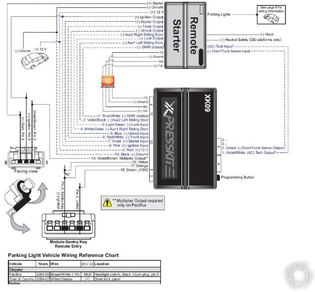
XK09 BYPass
Tech signal is programed
Transmission mode is in automatic.
when i run remote start shutdown/start up diagnostics
diagnostic
it told
low or no rpm
timer mode/turbo mode/ manual mode
low battery (voltage mode)
here is what i wire to
Main Harness 6pin
h1/1 red const 12v - ------ --- --- --- --- tap to a const 12v TN/WH BCM
h1/2 black grnd ----------------- ---- --- -- -- chassis ground Bk BCM
h1/3 brown siren out - -- - - ----------- --- connect to sirens red (black to ground)
h1/4 WHITE/ brown park light isolation wire ------- not used
h1/5 white park light out - -------------------- WHITE/ BROWN at head light switch
h1/6 orange ground when armed out -------------- Not used
Door lock 3 in
1 blue out - not used
2 empty
3 green - not used
Aux/shutdown/trigger harness, 24-pin connector
1 PNK/WHITE (-) 200mA Ignition 2/Flex OUTPUT - - - - - - - - Not used
2 BLUE/WHITE (-) 200mA 2ND STATUS /REAR DEFOGGER OUTPUT- - - - - - Not used
3 RED / WHITE (-) 200mA TRUNK RELEASE OUTPUT- - - - - - - - - Not used
4 BLACK / YELLOW (-) 200mA DOME LIGHT OUTPUT- - - - - - - - - - Not used
5 DARK BLUE (-) 200mA STATUS OUTPUT- - - - - - - - - - - - - - Not used
6 WHITE/ BLACK (-) 200mA AUX 3 OUTPUT- - - - - - - - - - - - Not used
7 WHITE/ VIOLET (-) 200mA AUX 1 OUTPUT- - - - - - - - - Not used
8 ORANGE / BLACK (-) 200mA AUX 4 OUTPUT- - - --- - Not used
9 GRAY (-) HOOD PIN INPUT (NC OR NO) - - - - - --- - - - -Hood pin
10 BLUE (-) TRUNK PIN/INSTANT TRIGGER INPUT (N/C OR N/O)- - - - Not used
11 WHITE/ BLUE ACTIVATION INPUT - - - - - - Not used
12 VIOLET/WHITE* TACHOMETER INPUT - - - - - Not used
13 BLACK/ WHITE** (-) NEUTRAL SAFETY /PARKING BRAKE INPUT - - - - - - Ground
14 GREEN/ BLACK (-) 200mA FACTORY ALARM DISARM OUTPUT- - - - - Not used
15 GREEN* (-) DOOR INPUT - - - - - - - - Not used
16 BROWN / BLACK (-) 200mA HORN HONK OUTPUT- - - - - - - Not used
17 PINK (-) 200mA IGNITION 1 OUTPUT - - - - - - Not used
18 VIOLET* (+) DOOR INPUT - - - - - - - Not used
19 VIOLET/BLACK (-) 200mA AUX 2 OUTPUT - - - - - - - - Not used
20 BROWN (+) BRAKE SHUTDOWN INPUT - - - - - - - - WHITE/ Tan at Brake switch
21 VIOLET / YELLOW (-) 200mA STARTER OUTPUT - - - - - - Not used
22 GRAY/BLACK (-) DIESEL WAIT TO START INPUT - - - - - - Not used
23 ORANGE (-) 200mA ACCESSORY OUTPUT - - - - - - - - Not used
24 GREEN / WHITE (-) 200mA FACTORY ALARM ARM OUTPUT - - - -- Not used
remote start 10 pin heavy gauge connector
1 NC No Connection- - - - - -- - - - -- - Not used
2 RED / BLACK (+) FUSED 12V ACCESSORY/STARTER INPUT- - - - - - - -- Not used
3 PINK/BLACK (+) FLEX RELAY INPUT 87A key side (if required) of FLEX RELAY- - - -Not used
4 PINK/WHITE (+) IGNITION 2 / FLEX RELAY OUTPUT- - - - - - - - Not used
5 RED (+) FUSED 12V IGNITION 1 INPUT - - - - - - - - - - - - - - - Not used
6 GREEN (+) STARTER INPUT (KEY SIDE OF THE STARTER KILL) - - - - YELLOW IGNITION SWITCH
7 VIOLET (+) STARTER OUTPUT (CAR SIDE OF THE STARTER KILL) - - - - - - Not used
8 ORANGE (+) ACCESSORY OUTPUT - - - - - - - - - - - - - - - - Not used
9 RED / WHITE (+) FUSED 12V IGNITION 2 / FLEX RELAY INPUT 87 - - - - - - - - Not used
10 PINK (+) IGNITION 1 INPUT/OUTPU - - - - - - - - - - - - - - PINK/WHITE IGNITION SWITCH


 Printable version


