Very long post!
Can you guys look this over and see if I have this right?
I am using an Avital 5303 and two 530T units. The functions I would like are pretty basic: arm/disarm with progressive door unlock, trunk unlock by remote and momentary switch under the dash, regular arm/disarm and remote starter operation.
On my car, a 1969 Dodge Charger, the climate control system is vacuum operated so I won't need to use any of the climate/defogger connections. I can just leave certain buttons depressed so when the car starts it's all up and running.
Besides having the windows roll up when arming the system, I may want a separate button to roll them up without arming the system. The alarm's H1/12 connects to either the 530T's H2/3 or H2/4 I think. DO I use the other for this function?
There are a few more Aux options I see but I wouldn't know what to use them for so I'm leaving them unused unless someone has any good ideas for them. I'm open to suggestions!
I have read the manuals front to back and looked all over this forum, but my car is not exactly typical so I still have a bunch of questions, some you can see in the wire description itself such as what to do with certain wires. I just want to make sure I have all this mapped out before I begin:
1. If I'm not using a certain wire, can I just tape it off?
2. Do I use the same fuse amps on the power wires close to the battery as those on the wire itself? For example H1/2 has a 15A fuse to protect the module, do I add a 15A fuse on the 10 gauge wire that goes from that wire to the battery or do I need a bigger fuse?
3. My dome light comes on when I open the door and goes off when I shut it. Is there a way to have the dome light go on when I disarm the car and shut off after I start it? Like a modern car?
4. Regarding IGN 1 and IGN2, I have a modern ignition system which required the coil to see 12v in both run and start positions so IGN1 and 2 have been soldered together. I'm assuming I no longer have to connect the wires for IGN2?
5. Without having to find a dealer, can I turn off the chirps when I arm/disarm the system? If I can, will all the other chirps be disabled as well? That may not be a good idea, what's your opinion on this.
➤ Primary harness (H1), 12-pin connector
H1/1 RED / WHITE (-) 200mA TRUNK RELEASE OUTPUT : to relay, momentary switch to same input as H1/1?
H1/2 RED (+) CONSTANT POWER INPUT : to + battery, fuse amp?
H1/3 BROWN (+) SIREN OUTPUT : to siren red wire
H1/4 EMPTY NOT USED
H1/5 BLACK (-) CHASSIS GROUND INPUT : chassis or negative battery terminal
H1/6 VIOLET (+) DOOR TRIGGER INPUT, ZONE 3
: unused? Door switch is ground when door open.
H1/7 BLUE (-) MULTIPLEXED INPUT, ZONE 4 : unused? No optional sensor only the one that came with the Avital.
H1/8 GREEN (-) DOOR TRIGGER INPUT, ZONE 3
: negative wire w/door open
H1/9 BLACK/ WHITE (-) 200mA DOMELIGHT SUPERVISION OUTPUT
: unused? no dome light supervision.
H1/10 WHITE/ BLUE (-) REMOTE START ACTIVATION INPUT : where does this wire go?
H1/11 WHITE (+)/(-) SELECTABLE LIGHT FLASH OUTPUT
: + parking lights wire
H1/12 ORANGE (-) 500mA ARMED OUTPUT : 530T H2/3 RED / white or H2/4 orange?
➤ Auxiliary harness (H2), 6-pin connector
H2/1 LIGHT BLUE (-) SECOND UNLOCK OUTPUT
: relay, passenger unlock actuator
H2/2 WHITE/ BLACK (-) AUX 2 OUTPUT
: unused?
H2/3 VIOLET/BLACK (-) AUX 1 OUTPUT
: unused?
H2/4 GREEN / WHITE (-) FACTORY ALARM REARM
: unused? No factory alarm
H2/5 GRAY/BLACK (-) WAIT-TO-START INPUT
: unused? No diesel
H2/6 LIGHT GREEN/ BLACK (-) FACTORY ALARM DISARM
: unused? no factory alarm
➤ Door lock harness, 3-pin connector
1 LIGHT BLUE (-) UNLOCK OUTPUT (+) LOCK
: relay, driver unlock actuator
2 EMPTY NOT USED
3 GREEN (-) LOCK (+) UNLOCK OUTPUT
: relay, both doors lock actuators
➤ Heavy gauge relay satellite wiring diagram
H/1 PURPLE STARTER OUTPUT TO STARTER (STARTER SIDE)
: starter wire going to starter
H/2 GREEN STARTER INPUT FROM IGNITION (KEY SIDE)
: starter wire going to ignition
H/3 RED (+) HIGH CURRENT 12V INPUT : to + battery, fuse amp?
H/4 ORANGE OUTPUT TO ACCESSORY CIRCUIT : vacuum operated climate so unused
H/5 PINK OUTPUT TO PRIMARY IGNITION CIRCUIT : ignition wire
H/6 RED (+) (30A) HIGH CURRENT 12V INPUT : unused?
H/7 PINK/WHITE OUTPUT TO SECOND IGNITION CIRCUIT : unused?
H/8 RED / WHITE (+) (30A) HIGH CURRENT 12V INPUT : unused?
➤ Remote start harness, (H3) 5-pin connector
H3/1 BLACK/ WHITE (-) NEUTRAL SAFETY SWITCH INPUT : to toggle switch, other switch wire grounded
H3/2 VIOLET/WHITE TACHOMETER INPUT WIRE : - side of coil
H3/3 BROWN (+) BRAKE SHUTDOWN INPUT WIRE
: brake switch + when depressed
H3/4 GRAY (-) HOOD PINSWITCH INPUT, ZONE 1
: hood pin switch
H3/5 BLUE/WHITE (-) 200 mA 2ND STATUS/REAR DEFOGGER - Latched Pulsed
: unused
➤ Horn, channel 6 (H4), 2-pin connector
H4/1 ORANGE / BLACK (-) AUX 3 OUTPUT
: where does this wire go?
H4/2 BROWN (-) 200 mA HORN
: to horn relay through SPDT relay?
Thanks for looking?


 I figured out the questions on fuses and such and where all the wires go. But I have a few more questions before I can install everything.
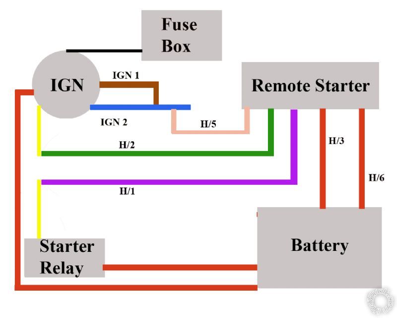
I drew up this crude schematic to show how I believe the RS is connected to this old ignition system.
The car used to have ignition 1 and 2 but due to installing a modern ignition system those wires have been connected. I still have one power wire coming in from the fuse box and one from the battery fused . As I understand, either ignition 1 or 2 would have power only in crank and the other would have power only in run. Since they are tied together it probably doesn't matter anymore and I should ignore the RS ignition 2 wires. I also don't have an accessory wire going to climate control or anything like that so that leaves only 5 wires to connect. Two 3oA fused power wires that go to the battery (H/3 & H/6), a pink wire going to the joined IGN1 and IGN2 wires (H/5). Lastly the green (H/2) and purple (H/1) wires that g to the cut wire that runs from ignition switch to starter relay.
Did I get it right?
I figured out the questions on fuses and such and where all the wires go. But I have a few more questions before I can install everything.
I drew up this crude schematic to show how I believe the RS is connected to this old ignition system.
The car used to have ignition 1 and 2 but due to installing a modern ignition system those wires have been connected. I still have one power wire coming in from the fuse box and one from the battery fused . As I understand, either ignition 1 or 2 would have power only in crank and the other would have power only in run. Since they are tied together it probably doesn't matter anymore and I should ignore the RS ignition 2 wires. I also don't have an accessory wire going to climate control or anything like that so that leaves only 5 wires to connect. Two 3oA fused power wires that go to the battery (H/3 & H/6), a pink wire going to the joined IGN1 and IGN2 wires (H/5). Lastly the green (H/2) and purple (H/1) wires that g to the cut wire that runs from ignition switch to starter relay.
Did I get it right?
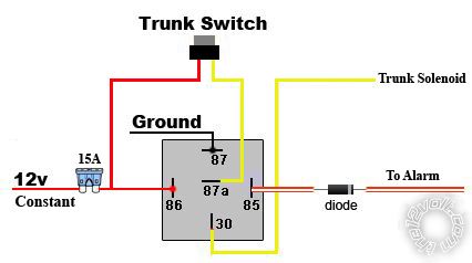
 I also found a few diagrams on how to wire the trunk popper relay and adapted it to this. I think this is how it's supposed to be. Would there be any point in wiring the power for the dash switch to key on power only instead of constant power? I can't think of any but thought I'd ask.
 I'm not sure what to do with the dome light. If anything I'd like it to light up when I unlock the car and turn off when I start it, but I don't know if it's possible. I may just leave it alone if it's too much trouble.
I decided not to use the siren that came with the Avital 5303. I don't like it and I really don't care for the chirps. I just want the parking lights to flash when I arm/disarm.
I do want the horn to pulse when the alarm is triggered so can I simply leave the siren unhooked and use the H4/2 horn output? It's a 200mA feed and my horns are already tied to a horn relay (stock). If I add this wire to it will it give me a pulsed output? There's no explanation in the manual about what this does. There's also H4/1 but that's an Aux 3 output and I don't know what it's for.
I'm not sure what to do with the dome light. If anything I'd like it to light up when I unlock the car and turn off when I start it, but I don't know if it's possible. I may just leave it alone if it's too much trouble.
I decided not to use the siren that came with the Avital 5303. I don't like it and I really don't care for the chirps. I just want the parking lights to flash when I arm/disarm.
I do want the horn to pulse when the alarm is triggered so can I simply leave the siren unhooked and use the H4/2 horn output? It's a 200mA feed and my horns are already tied to a horn relay (stock). If I add this wire to it will it give me a pulsed output? There's no explanation in the manual about what this does. There's also H4/1 but that's an Aux 3 output and I don't know what it's for.
 Printable version


