2011 Hyundai Elantra Remote Start Pictorial

This info should be applicable to the 2011 thru 2015 Elantra's built for the U.S. market. The car in this pictorial is a 2011
with power locks, Factory Alarm and automatic transmission. As a U.S. market vehicle, it has no transponder immobilizer
system. This car did not have automatic headlights.
Due to the Factory Alarm system, the fact that the Factory Remotes are disabled during remote start engine run time and
that the car ignores unlock commands from the door switch after the alarm sets, special consideration must be made during
R/S system selection. To make this a quick and easy install we will use some excellent information provided by fellow
12Volt member Chris Luongo in this post :
https://www.the12volt.com/installbay/forum_posts.asp?tid=138331 Using this
info allows us to omit the extra relays and diodes typically required for this vehicle.
R/S system requirements / considerations:
Remote start with keyless entry ( 4 button remotes )
Able to support one Starter, one Ignition and two Accessory wires.
Able to be programmed for :
1. Double Lock pulse output
2. Double Unlock pulse output
3. Double Disarm pulse output
4. (-) Trunk Release output that is preceded with a Disarm
There are several basic R/S systems that can do this. For this install an Avital 4103LX was the choice. Another good
choice is the Compustar CS800-s.
Disassembly ( there is a bit to remove but Hyundai's are very straight forward ) :
Remove the driver side dash panel using a non-marring trim tool.
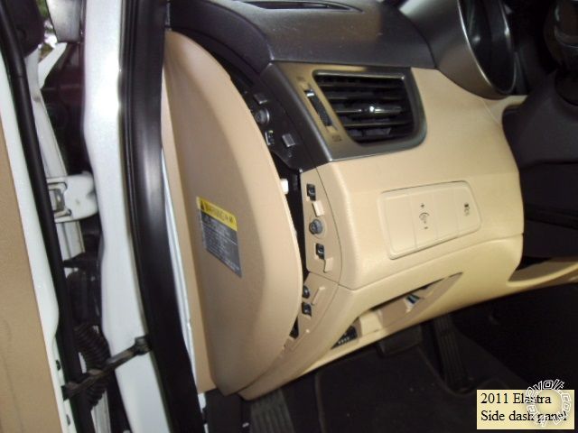
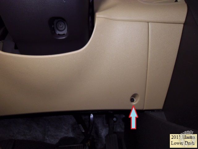
Remove the one Phillips screws on the lower dash panel indicated.
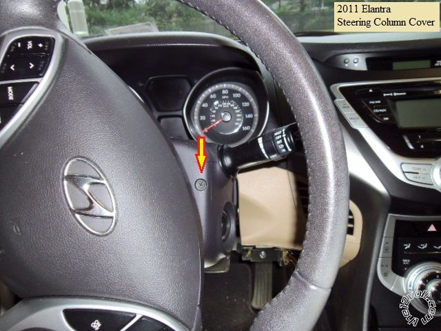
Remove the two Phillips screws shown in the photo below ( yellow arrows ).
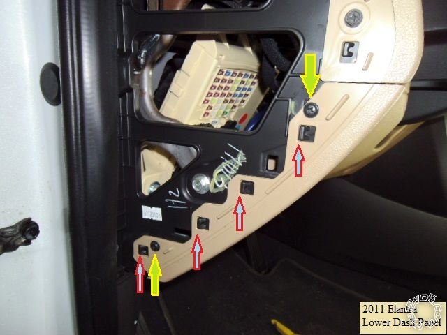
Using a screwdriver blade, release the 4 tabs indicated with red arrows above and pull the lower dash panel straight away.
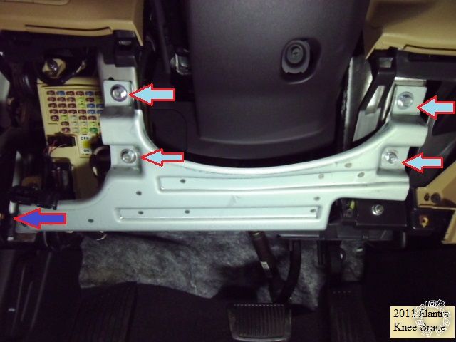
Remove the now exposed knee brace by removing the four 10mm bolts and the one 10mm nut pictured below.
Next, rotate the steering wheel to remove the 2 Phillips screws at 10 and 2 o'clock positions shown below.
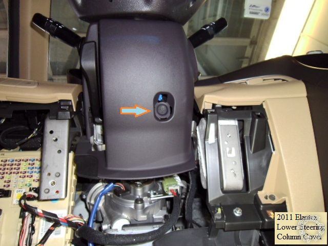
Remove the one Phillips screw shown in the lower steering column cover, then squeeze in at the side seams to separate
the two halves and remove the lower cover.
To remove the drivers kick panel, gently lift up the driver door sill trim and remove. The hood release level is removed by
squeezing the center fingers while applying pressure under the level to pop it off the shaft. Then pull the DKP straight back.
Wires :
The Brake and Horn wires are found in the DKP. Below is the Brake wire found in the White 56 Pin plug.
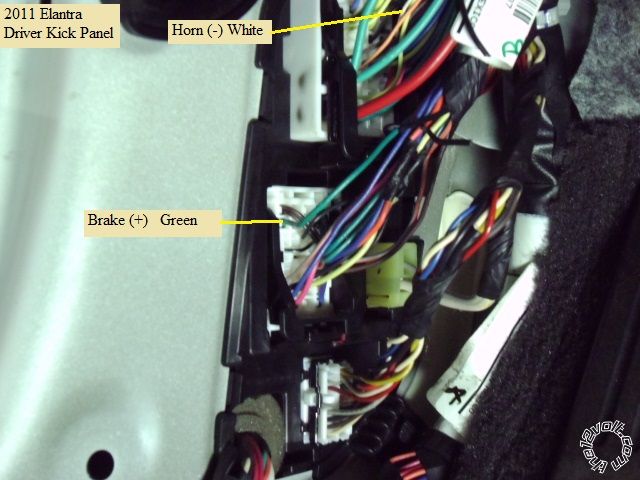
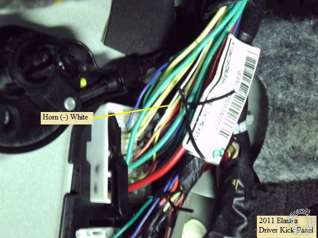
The Horn wire ( very thin ) is in the White 55 pin plug just above the Brake wire.
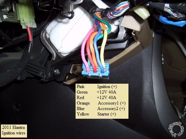
These are the main ignition wire found at the ignition switch in the steering column.
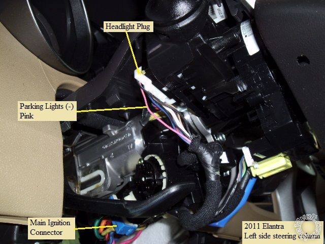
This the the Parking Light wire at the Headlight switch connector.
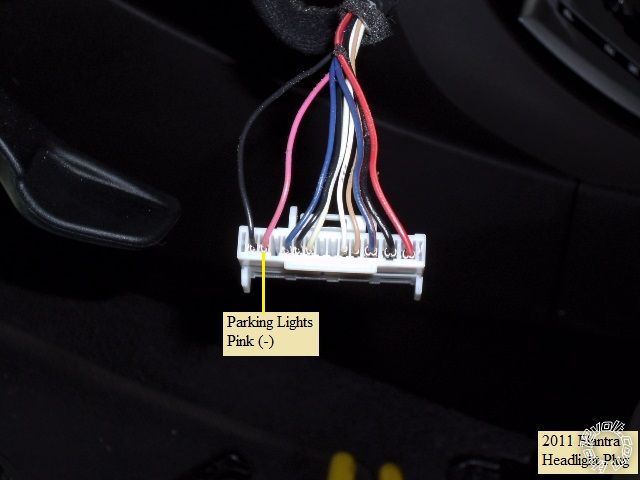
And here is a close-up of the Parking Light wire.
Below is a shot of the dash fuse box with the important area's noted.
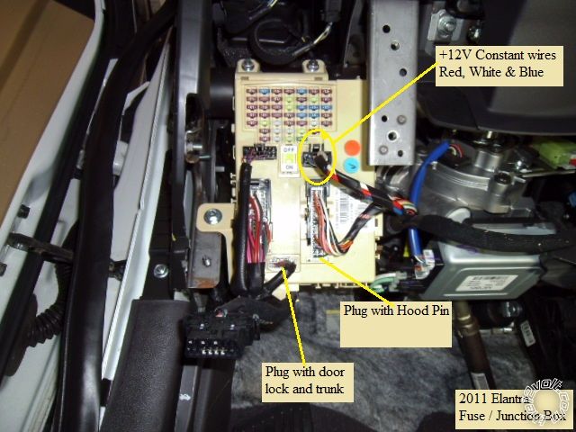
The hood pin is pictured below.
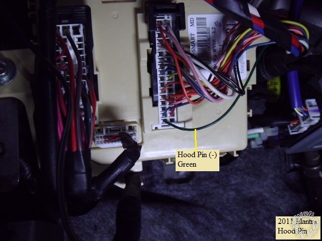
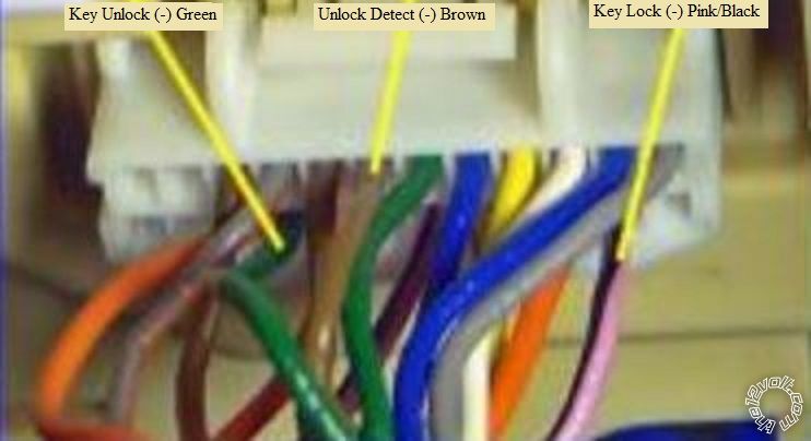
The White 24 Pin plug has many important connections. Here are 3 wires in the photo below.
Next is a diagram of the White 24 Pin Plug with the necessary wires indicated.
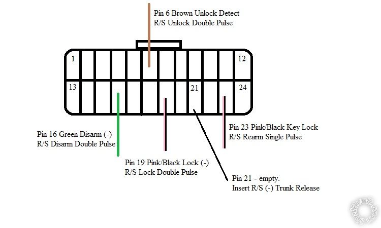
Typical installs will include a relay to convert the R/S's (-) Trunk Release output to a strong (+) output and connect to the
Red (+) Trunk Release wire ( White 39 Pin Plug, Pin 38 ) at the Dash Fuse Box but is it possible to allow the R/S to control
the trunk via a direct connection to the empty pin shown. An easy way mentioned by Chris, is to strip about 3/4 inch of
insulation from the R/S's (-) Trunk Release output wire, tightly twist it and firmly insert it into the empty pin hole. Secure this
wire to an adjacent wire with a couple tie wraps. Another way is to obtain this plug from a salvage yard and transfer a pin into
the connector's empty pin hole, then solder on the R/S's Trunk Release wire.
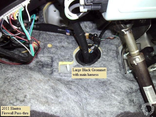
Firewall pass through for Tach wire can be found at the large grommet that is used by the main engine compartment
harness pictured below.
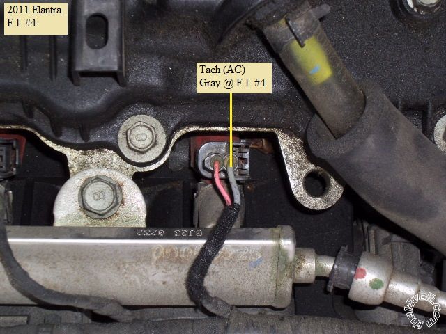
After lifting off the engine cover ( 4 pins ), the Tach source can be found at the #4 Fuel Injector shown next.
Here is the wiring used with the Avial 4103LX remote start system :
H1/1 LIGHT GREEN/ BLACK FACTORY ALARM DISARM Green wire @ Fuse Box White 24 Pin Plug, Pin 16
H1/2 GREEN / WHITE FACTORY REARM Pink/Black wire @ Fuse Box White 24 Pin Plug, Pin 23
H1/3 YELLOW (+) IGNITION OUT (TO ALARM) not used
H1/4 WHITE/ BLUE (-) ACTIVATION INPUT not used
H1/5 ORANGE (-) GROUND WHEN LOCKED not used
H1/6 BROWN (-) HORN OUTPUT White wire @ DKP White 55 Pin Plug, Pin 44
H1/7 RED / WHITE (-) TRUNK RELEASE OUTPUT Empty Pin @ Fuse Box White 24 Pin Plug, Pin 21
H1/8 BLACK GROUND Chassis Ground
H1/9 WHITE (+/-) LIGHT FLASH *Set to (-) Pink wire @ Headlight connector, White 13 Pin, Pin 2
H2/1 BLACK/ WHITE (-) NEUTRAL SAFETY SWITCH INPUT Chassis Ground through valet switch
H2/2 VIOLET/WHITE TACHOMETER INPUT WIRE F.I. #4, Gray wire
H2/3 BROWN (+) BRAKE SWITCH SHUTDOWN WIRE Green wire @ DKP White 56 Pin Plug, Pin 10
H2/4 GRAY (-) HOOD PINSWITCH SHUTDOWN WIRE Green wire @ Fuse Box White 34 Pin Plug, Pin 34
H2/5 BLUE/WHITE (-) 200mA 2ND STATUS/REAR DEFOG not used
4-pin satellite harness diagram
1 BLUE STATUS OUTPUT not used
2 ORANGE (-) ACCESSORY OUTPUT not used
3 PURPLE (-) STARTER OUTPUT not used
4 PINK (-) IGNITION OUTPUT not used
Heavy gauge relay wiring diagram
1 PINK (+) (30 AMP) OUTPUT TO IGNITION CIRCUIT Pink wire @ ignition switch harness
2 PURPLE (+) (30 AMP) OUTPUT TO STARTER CIRCUIT Yellow wire @ ignition switch harness
3 ORANGE (+) (30 AMP) OUTPUT TO ACCESSORY CIRCUIT Orange wire @ ignition switch harness
4 RED (+) (30A) HIGH CURRENT 12 INPUT Red wire @ ignition switch harness
5 PINK/WHITE (+) PROGRAMMABLE OUTPUT *Set to ACC2 Blue wire @ ignition switch harness
6 RED (+) (30A) HIGH CURRENT 12V INPUT Green wire @ ignition switch harness
Door lock harness, 3-pin connector
1 BLUE (-) UNLOCK OUTPUT Brown wire @ Fuse Box White 24 Pin Plug, Pin 6
2 EMPTY NOT USED
3 GREEN (-) LOCK OUTPUT Pink/Black wire @ Fuse Box White 24 Pin Plug, Pin 19
Avital Programming changes :
Menu 1, Feature 1 to Option 2 Horn Honk length ( optional )
Menu 1, Feature 5 to Option 2 Double Unlock pulse
Menu 1, Feature 6 to Option 2 Double Lock pulse
Menu 1, Feature 8 to Option 2 Double Factory Alarm Disarm pulse
Menu 2, Feature 1 to Option 4 Tach Mode ( must also do Tach Learn )
Menu 2, Feature 6 to Option 2 Flex relay = ACC2
There is plenty of room for R/S placement behind the fuse box and under the dash. Remember to test all wires with a
Digital Multi Meter prior to making quality solder connections. Also allow proper wire relief to the wires going to steering
column connections due to the tilt / telescopic steering wheel.
Soldering is fun!


 Topic Closed)


 Printable version


