the12volt.com spacer
icon

Viper 4105 2009 Chevy Aveo


Post ReplyPost New Topic
< Prev Topic Next Topic >
chev104275 
Gold - Posts: 1,419
Gold spaceThis member has been recognized as an authority in Mobile Security and Convenience. Click here for more info.spacespace
Joined: November 26, 2007
Location: Massachusetts, United States
Posted: September 01, 2017 at 9:17 AM / IP Logged Link to Post Post Reply Quote chev104275
The only thing on the 9 pin you would need is ground. Do you have the antenna plugged in ? Do you get any reaction using a remote ? Are the parking lights hooked up ? Do they flash when using the remote ?
If i Can't Install it    I Don't need it   Joe
dacker 
Copper - Posts: 60
Copper spacespace
Joined: May 08, 2017
Location: Alabama, United States
Posted: September 01, 2017 at 9:27 AM / IP Logged Link to Post Post Reply Quote dacker
Don't have the parking lights hooked up yet but I will this evening and see but as of yet remote does nothing. I do have the ground hooked up though.
chev104275 
Gold - Posts: 1,419
Gold spaceThis member has been recognized as an authority in Mobile Security and Convenience. Click here for more info.spacespace
Joined: November 26, 2007
Location: Massachusetts, United States
Posted: September 01, 2017 at 1:29 PM / IP Logged Link to Post Post Reply Quote chev104275
Weird I would hook up both reds to 12v , ground, pink to ignition, parking lights, plug in the antenna and see what happens
If i Can't Install it    I Don't need it   Joe
dacker 
Copper - Posts: 60
Copper spacespace
Joined: May 08, 2017
Location: Alabama, United States
Posted: September 01, 2017 at 8:19 PM / IP Logged Link to Post Post Reply Quote dacker
Ok here's what i got... On the heavy gauge wire I have
-both reds with 12v battery going directly to them.
The pink wire to ignition wire
The pink and white to second ignition (off during crank)
Purple to starter
Orange not used
I grounded the black wire on the 9 pin harness
What I have in return is this:
    On the heavy gauge harness:
-The pink and white will go off during crank
-the solid pink stays on even during crank as long as ignition is on
-The reds stay hot all the time
     In the 9 pin harness:
-the yellow stays hot as long as the ignition switch is on
-nothing on the rest of them even pushing every button on the remote.
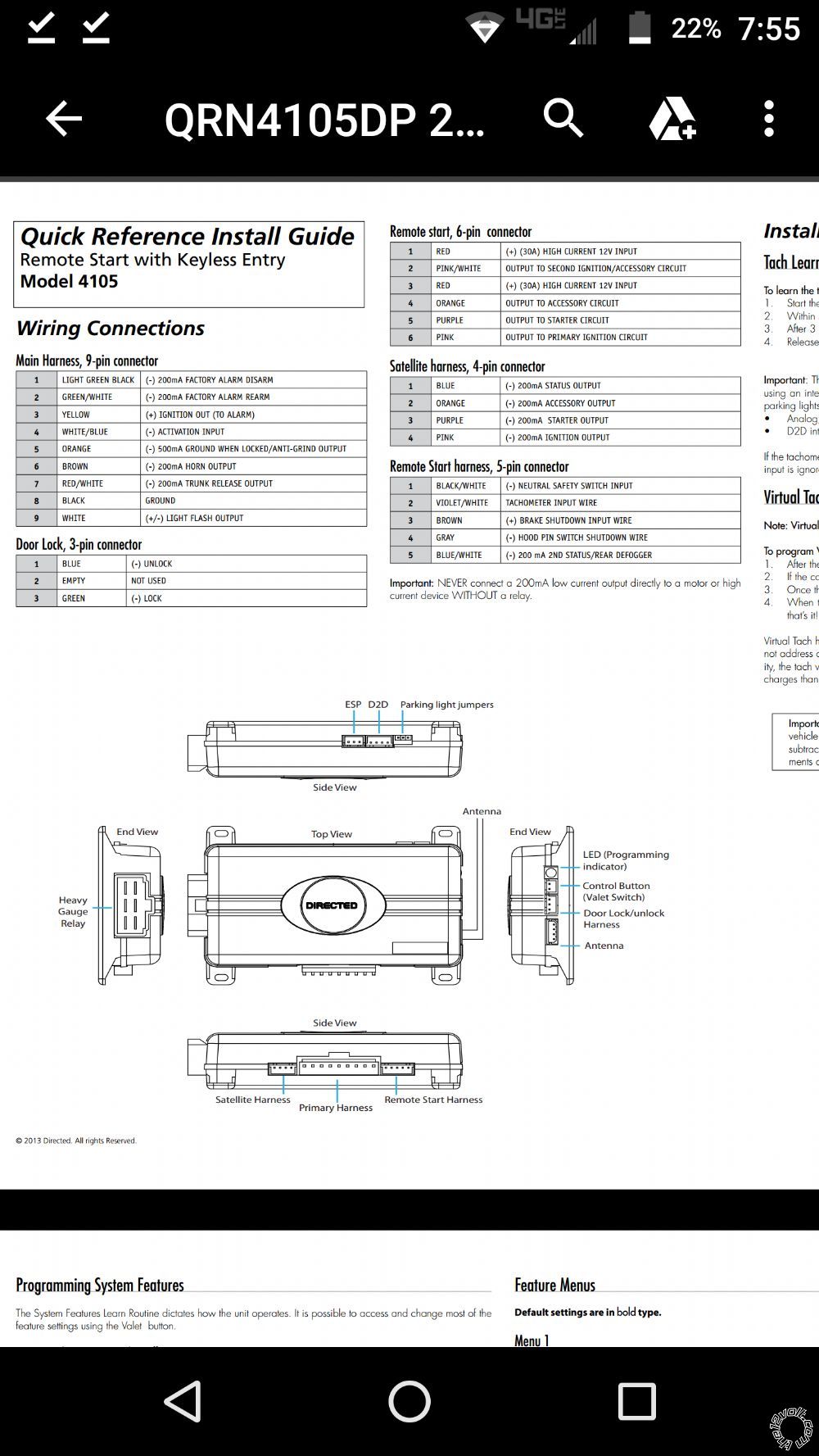
This is where is gets interesting. Absolutely none of the other wires get 12v at any time even pushing every button on the remote. I am using a 12v probe like to check all this. The kind you clip the ground to the negative battery and probe what you want and if it has voltage the little light will come on. Now what will happen is when I get to the satellite harness and probe pin 3 (labled 200ma starter output) I will hear a click in the brain box and if the vehicle is running it will stay running even if I turn the key if and take it out. It will run until I pull the probe light off of the wire (thus ungrounding it) then the vehicle will shut off. Outside of that I have nothing else and no action from the led light. And I checked all these pushing every button on the remote with the antenna plugged in along with all the rest of the plugs. The only thing that is not hooked up is the little toggle switch that came with it but there is no plug on the end of it just 2 blank end wires. Here's the diagram I'm going by.
Viper 4105 2009 Chevy Aveo - Page 2 -- posted image.
dacker 
Copper - Posts: 60
Copper spacespace
Joined: May 08, 2017
Location: Alabama, United States
Posted: September 01, 2017 at 8:50 PM / IP Logged Link to Post Post Reply Quote dacker
Ok update.... Got the led working and am able to go in programming mode and all. I did figure out I think there are a couple of issues. #1 even though the led seems to be functioning fine with the programming and valet button the horn output never gets a signal and it's supposed to during the programming process (Brown wire on 9 pin harness). Additionally when trying to program either if the remotes that came with it neither of them seem to be getting signal to the unit. Everything works up until I am to hold down the lock button until the unit receives the signal which it never does. The led just keeps blinking twice fast then pause and with do that for about 30 seconds or so and then quit all together. Seems like I did read someone's post that had to swap their antenna out bc it was the wrong one or something but I'm beginning to wonder if it isn't the unit itself since the horn isn't getting an output signal. What would be the next steps in the arsenal to take?
dacker 
Copper - Posts: 60
Copper spacespace
Joined: May 08, 2017
Location: Alabama, United States
Posted: September 02, 2017 at 3:34 PM / IP Logged Link to Post Post Reply Quote dacker
Ok still stuck but doing some research apparently I have to have the door open signal hooked up to program this thing however I see nothing on the diagram that says anything about a door or dome light or whatever. I feel I am getting closer but need a little direction from this point please.
chev104275 
Gold - Posts: 1,419
Gold spaceThis member has been recognized as an authority in Mobile Security and Convenience. Click here for more info.spacespace
Joined: November 26, 2007
Location: Massachusetts, United States
Posted: September 02, 2017 at 6:03 PM / IP Logged Link to Post Post Reply Quote chev104275
Where did you get this system from ? New or used ? How are you testing the horn output ? If using a meter it might not be fast enough to see the 20 milisecond pulse. Every new DEI system I've got always comes with the remotes programmed. As far as needing to see the door open to program. There is no input on that system to do that so I think maybe your confusing systems.
If i Can't Install it    I Don't need it   Joe
dacker 
Copper - Posts: 60
Copper spacespace
Joined: May 08, 2017
Location: Alabama, United States
Posted: September 05, 2017 at 11:32 AM / IP Logged Link to Post Post Reply Quote dacker
OK tons of progress!!!! Only one issue now. I have the system programmed to the remote and everything functioning with the exception of the starter getting a signal. I can run a wire straight to the starter from the other side of the out side of the 2 relays that is connected to the orange wire and it will start the car but as long as that wire is touching the starter continues to turn. additionally I can ground the same place and the system will work exactly like its supposed to but the car will not shut off until I remove the ground. Even with the key removed. So this tell me I am extremely close I just have a wire or 2 wrong somewhere. SO given the diagrams can you all tell me exactly what wires land to exactly where on the relays? Also what all needs to be run just straight to the chassis ground. Thanks Dale
chev104275 
Gold - Posts: 1,419
Gold spaceThis member has been recognized as an authority in Mobile Security and Convenience. Click here for more info.spacespace
Joined: November 26, 2007
Location: Massachusetts, United States
Posted: September 06, 2017 at 6:59 PM / IP Logged Link to Post Post Reply Quote chev104275
What pin on the relay are you grounding ?   How close to the measured value did you get the resistor ?
If i Can't Install it    I Don't need it   Joe
dacker 
Copper - Posts: 60
Copper spacespace
Joined: May 08, 2017
Location: Alabama, United States
Posted: September 06, 2017 at 7:24 PM / IP Logged Link to Post Post Reply Quote dacker
I am following the diagram posted earlier to a tee for the pass lock bypass so whichever one of those is considered grounded, other than I wasn't sure which wire to put in the middle of the relays labled ignition 3 so nothing is on it. The measured value I got was 1.8 and I have a 1.3 on here.
Page of 4

  Printable version Printable version Post ReplyPost New Topic
You cannot post new topics in this forum
You cannot reply to topics in this forum
You cannot delete your posts in this forum
You cannot edit your posts in this forum
You cannot create polls in this forum
You cannot vote in polls in this forum

  •  
Search the12volt.com
Follow the12volt.com Follow the12volt.com on Facebook
Thursday, March 28, 2024 • Copyright © 1999-2024 the12volt.com, All Rights Reserved Privacy Policy & Use of Cookies
Disclaimer: *All information on this site ( the12volt.com ) is provided "as is" without any warranty of any kind, either expressed or implied, including but not limited to fitness for a particular use. Any user assumes the entire risk as to the accuracy and use of this information. Please verify all wire colors and diagrams before applying any information.

Secured by Sectigo
the12volt.com spacer
Support the12volt.com
Top
the12volt.com spacer