the12volt.com spacer
icon

Avital Remote Start Install, 03 Ford F-250


Post ReplyPost New Topic
< Prev Topic Next Topic >
reptar 
Member - Posts: 12
Member spacespace
Joined: September 29, 2017
Location: Washington, United States
Posted: September 30, 2017 at 2:30 PM / IP Logged Link to Post Post Reply Quote reptar
kreg357 wrote:
If you don't have RKE, now would have been to time to add it. Not much of a price difference between the
Viper 4115 and the 4105. You can still get some extra bang for your buck by adding the Viper 4115 Unlock
while remote started feature. If your truck does not have Factory RKE, you will need another 30/40 Amp
SPDT relay.
Man kreg357 thank you so much for coping and updating my wiring codes!
My trucks a gasser so I can still tap into that Ignition coil wire above spark plugs & not behind my cluster?
Also yes I'm going to ask, what is RKE?? A unlock/lock key fob?
I have the factory unlock & lock remote & don't you have to had a relay for the unlock & lock function to work? Figured its less
cutting into my wires & simpler without.
reptar 
Member - Posts: 12
Member spacespace
Joined: September 29, 2017
Location: Washington, United States
Posted: September 30, 2017 at 2:34 PM / IP Logged Link to Post Post Reply Quote reptar
kreg357 wrote:
Satellite Harness White 4-Pin Connector (DON’T BELIEVE I USE)
1.BLUE      (-) 200ma Status Output       not used unless truck has PATS
2.ORANGE (-) 200ma Accessory Output     to extra realy, Pin 85 for ACC2 wire
3.PURPLE (-) 200ma Starter output     not used
4.PINK   (-) 200ma Ignition Output      not used
Extra 30/40 Amp SPDT relay for ACC2
Relay Pins 86 and 87 to Yellow #2 at ignition harness through 30 amp fuse
Relay Pin 85 to Viper Orange at Pin 2 of Satellite plug
Relay Pin 30 to ACC2 DARK BLUE/LIGHT GREEN (+) @ IGNITION SWITCH HARNESS
So I only use this if I have pats correct?
reptar 
Member - Posts: 12
Member spacespace
Joined: September 29, 2017
Location: Washington, United States
Posted: September 30, 2017 at 2:44 PM / IP Logged Link to Post Post Reply Quote reptar
Also yes I would like anti-grind for my peace of mind. That just means I have to hook up the tach wire right?
Also sorry I would of tried to keep this forum cleaner but I cant find any edit button for my posts. Seems like you have to upgrade your account for it?
Thanks!
reptar 
Member - Posts: 12
Member spacespace
Joined: September 29, 2017
Location: Washington, United States
Posted: September 30, 2017 at 3:43 PM / IP Logged Link to Post Post Reply Quote reptar
**UPDATED** NO CHIPPED KEY, 5.4 GAS AUTO TRANS.
Primary Harness, White 9-pin Connector
1. LIGHT GREEN BLACK (-) 200ma Factory Alarm Disarm Output      (NOT USED)
2. GREEN/WHITE     (-) 200ma Factory Alarm Rearm Output      (NOT USED)
3. YELLOW     (+) Ignition Out (To Alarm)                (NOT USED)
4. WHITE/BLUE     (-) Activation input                     (NOT USED)
5. ORANGE     (-) 500ma Ground when locked/anti-grind output ???? STILL DONT GET?
6. BROWN     (-) 200ma Horn output      (Dark Blue/ Steering Column)
7. RED/WHITE      (-) 200ma Trunk Release output           (NOT USED)
8. BLACK     (-) Chassis Ground                (Any ground under dash)
9. WHITE     (+/-) Light flash Output      (+ Brown, Headlight Switch)
Remote Start Harness, White 5-Pin Connector
1.BLACK/WHITE     (-) Parking Brake Input**          TO CHASSIS GROUND
**(Connect this wire the the (-) Parking brake wire in the vehicle. The parking brake must be applied for the remote start to work.)
2.VIOLET/WHITE Tachometer Input      (IGNITION COIL WIRE/ NOT RED/LIGHT GREEN
3.BROWN     (+) Brake Shutdown Input     (Light Green (+) Brake Pedal)
4.GRAY     (-) Hood Pin Switch Shutdown Input     (Supplied Switch)
5.BLUE/WHITE     (-)200ma 2nd Status/Rear Defogger Output (NOT USED)
Heavy Gauge Relay, White 6-Pin Connector
1.RED (+) (30A) High Current 12V Input           (12 Constant/ Yellow (+) Ign.)
2.PINK/WHITE     (+)Second Ignition/accessory Cir. Output RED/BLACK(+) IGN
3.RED     (+)(30A) High Current 12v Input (Constant/ Light Green Purple
4.ORANGE     (+)Accessory Output      GREY/YELLOW IGN
5.PURPLE     (+)Starter Output          (Starter Wire Green)
6.PINK          (+) Ignition 1 Input/output      (White/Yellow)
Satellite Harness White 4-Pin Connector (DON’T BELIEVE I USE)
1.BLUE     (-) 200ma Status Output
2.ORANGE (-) 200ma Accessory Output
3.PURPLE (-) 200ma Starter output
4.PINK (-) 200ma Ignition Output
Door Lock, White 3-Pin Connector (NOT USING)
1.LIGHT BLUE (-) 200ma Unlock Output
2.EMPTY
3.GREEN (-) 200ma Lock Output
D2D Harness, Red 4-Pin Connector (NOT USING)
1.BLUE      D2D –TX
2.BLACK (-) Ground
3.GREEN D2D – RX
4.RED      (+) 12v
Bitwriter/ Directed Smartstart Harness, Black 3-Pin Connector (NOT USING)
1.RED (+) 12v
2.ORANGE ESP2 – RX/TX
3.BLACK (-) Ground
kreg357 
Platinum - Posts: 7,783
Platinum spaceThis member has made a donation to the12volt.com. Click here for more info.spaceThis member has been recognized as an authority in Electrical Theory. Click here for more info.spaceThis member has been recognized as an authority in Mobile Security and Convenience. Click here for more info.spacespace
Joined: January 30, 2009
Location: Pennsylvania, United States
Posted: September 30, 2017 at 4:44 PM / IP Logged Link to Post Post Reply Quote kreg357
No chipped keys means you don't need a bypass module or use the Blue (-) Status Output wire. The 4115 and the extra relay
will handle everything.
The extra relay will be used in conjunction with the Vipers thin (-) Accessory output wire to power the trucks ACC2 wire.
The wiring was shown above. This extra ACC wire has nothing to do with PATS and chipped keys. I would still power
ACC2 but you can try it without. It might only power the radio, wipers, windows and unnecessary things like that.
The TACH connection will allow the Viper to crank the engine enough to start but not too long to get that drag over-run.
This is a good feature if you have big seasonal temperature swings. A cold day with a cold engine usually requires extra
crank time to get it running. Much more reliable than Virtual Tach.
The Anti-Grind feature mentioned is to prevent you from engaging the starter again during key-takerover if you were
to turn the key too far. It's optional and would require another 30/40 Amp relay and extra wiring using (-) Status Output.
Using Ground When Locked won't really work with a 4115 because your Viper one button FOB doesn't do Lock.
RKE means Remote Keyless Entry, as in the Ford FOB's that will lock and unlock the truck at a short distance.
If you have RKE, you could use the 4115 feature that allows you to use the single button FOB to unlock the doors
while the truck is remote started. All that would be needed is a direct connection from the 4115 (-) Unlock wire to
the trucks Unlock wire. Without factory RKE, you would need another 30/40 Amp SPDT relay to interface with
the trucks Unlock wire ( 5 wire reverse vs (-) Type B locking system ).
Soldering is fun!
reptar 
Member - Posts: 12
Member spacespace
Joined: September 29, 2017
Location: Washington, United States
Posted: September 30, 2017 at 8:24 PM / IP Logged Link to Post Post Reply Quote reptar
kreg357 wrote:
The 4115 and the extra relay will handle everything.
The extra relay will be used in conjunction with the Vipers thin (-) Accessory output wire to power the trucks ACC2 wire.
The wiring was shown above. This extra ACC wire has nothing to do with PATS and chipped keys. I would still power
ACC2 but you can try it without. It might only power the radio, wipers, windows and unnecessary things like that.
The TACH connection will allow the Viper to crank the engine enough to start but not too long to get that drag over-run.
This is a good feature if you have big seasonal temperature swings. A cold day with a cold engine usually requires extra
crank time to get it running. Much more reliable than Virtual Tach.
The Anti-Grind feature mentioned is to prevent you from engaging the starter again during key-takerover if you were
to turn the key too far. It's optional and would require another 30/40 Amp relay and extra wiring using (-) Status Output.
Using Ground When Locked won't really work with a 4115 because your Viper one button FOB doesn't do Lock.
K I think I've got most of that!
Defiantly going to run the Tach wire as winter is approaching & it can get pretty cold here in the Pacific Northwest on occasion.
If I wanted I would need two extra relays,
1. To power my accessories, radio, blower mabye? ect.
2. Another relay to use the Anti-Grind feature during key takeover.
If you or anyone else is up to it, could you explain how to wire the relays?
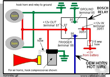
So I believe this is the correct type of relay image I've found.
So for
1. My accessories I would
85 -Run To Ground
87 -2nd trucks accessory wire?
86 trigger with (Satellite Harness White 4-Pin Connector
2.ORANGE (-) 200ma Accessory Output)
30/51- Power for 12v+ from battery or other source
For anti-grind feature I would
85-to ground
87- Primary Harness, White 9-pin Connector5. ORANGE (-) 500ma Ground when locked/anti-grind output
86-Trigger with (Satellite Harness White 4-Pin Connector
1.BLUE(-) 200ma Status Output)
30/51- Power for 12v+ from battery or other source
Avital Remote Start Install, 03 Ford F-250 - Page 2 -- posted image.
kreg357 
Platinum - Posts: 7,783
Platinum spaceThis member has made a donation to the12volt.com. Click here for more info.spaceThis member has been recognized as an authority in Electrical Theory. Click here for more info.spaceThis member has been recognized as an authority in Mobile Security and Convenience. Click here for more info.spacespace
Joined: January 30, 2009
Location: Pennsylvania, United States
Posted: September 30, 2017 at 11:13 PM / IP Logged Link to Post Post Reply Quote kreg357
One of the relays would be used to power the trucks ACC2 circuit. I am not sure what is controlled by
the ACC2 circuit. It could be things like radio, power windows, wipers, etc. Might not be those items.
I have never tried to find out as I always power it. This ACC2 relay would be wired as below :
Relay Pin 86 and 87 to +12V constant Yellow #2 at the ignition switch through 30 Amp fuse
Relay Pin 85 to Avital 4115 thin Orange (-) Accessory Output
Relay Pin 30 to ACC2 DARK BLUE/LIGHT GREEN (+) @ IGNITION SWITCH HARNESS
Relay Pin 87a not used
This was shown on Page 1.
The second relay would be for the optional Anti-Grind. This feature would reguire you to cut the trucks
Dark Green Starter wire and make a slight wire deviation from the previously posted listing. It would be
wired as below :
Relay Pin 85 to Avital Dark Blue (-) Status Output
Relay Pin 86 to +12V constant ( either Yellow or the Light Green/Violet wire )
Relay Pin 87a to ignition switch side of cut Dark Green Starter wire
Relay Pin 30 to vehicle side of cut Dark Green Starter wire
Relay Pin 87 to Avital thick (+) Purple Starter Output
Please note that the Avital thick (+) Purple Starter Output wire must connect to the vehicle side of the cut
Dark Green Starter wire.   It could go to Pin 30 of the Relay also, but then you would have to connect two
wires to Pin 30. It is easier to use the energized relay's Pin 87 to send the Starter signal to the truck.
How the Anti-Grind relay works :
During normal key start up, the relay is in a de-energized state. As such Pins 30 and 87a are NC ( normally
closed ) and will allow the +12V Starter signal from the ignition switch through and the starter will crank.
During a remote start, the (-) Status Output signal goes true and outputs a Chassis Ground during the entire
remote start sequence. This (-) Status output signal energizes the relay and opens its' internal connection
between Pins 87a to 30 and makes the connection between Pin 87 and 30. This does two things. It prevents
the ignition switch (+) Starter signal from getting through the relay and cranking the starter motor. It
allows the Avitals Starter Output to go from Pin 87 to Pin 30 and on to the starter motor to start the engine.
The Anti-Grind feature works because the relay is energized during the entire remote start period, so if you
get into the truck, insert the key into the ignition switch and inadvertly go past ON and hit the START area,
the ignition switches +12V Starter signal would not go through the open relay contacts ( Pin 87a to 30 )
and cause a starter grind.
Soldering is fun!
kreg357 
Platinum - Posts: 7,783
Platinum spaceThis member has made a donation to the12volt.com. Click here for more info.spaceThis member has been recognized as an authority in Electrical Theory. Click here for more info.spaceThis member has been recognized as an authority in Mobile Security and Convenience. Click here for more info.spacespace
Joined: January 30, 2009
Location: Pennsylvania, United States
Posted: September 30, 2017 at 11:29 PM / IP Logged Link to Post Post Reply Quote kreg357
Updated wiring with ACC2 and Anti-Grind relays.
Primary Harness, White 9-pin Connector
1. LIGHT GREEN BLACK (-) 200ma Factory Alarm Disarm Output      (NOT USED)
2. GREEN/WHITE     (-) 200ma Factory Alarm Rearm Output      (NOT USED)
3. YELLOW     (+) Ignition Out (To Alarm)                (NOT USED)
4. WHITE/BLUE     (-) Activation input                     (NOT USED)
5. ORANGE     (-) 500ma Ground when locked/anti-grind output   (NOT USED)
6. BROWN     (-) 200ma Horn output      (Dark Blue/ Steering Column)
7. RED/WHITE      (-) 200ma Trunk Release output           (NOT USED)
8. BLACK     (-) Chassis Ground                (Any solid rust/paint free area of frame using soldered-on terminal ring)
9. WHITE     (+/-) Light flash Output  *    (+ Brown, Headlight Switch)
* Set 4115 Parking Light jumper to (+) output
Remote Start Harness, White 5-Pin Connector
1.BLACK/WHITE     (-) Parking Brake Input        TO CHASSIS GROUND
2.VIOLET/WHITE Tachometer Input      (any IGNITION COIL WIRE that is NOT RED/LIGHT GREEN)
3.BROWN     (+) Brake Shutdown Input     (Light Green (+) Brake Pedal switch)
4.GRAY     (-) Hood Pin Switch Shutdown Input     (Supplied Switch)
5.BLUE/WHITE     (-)200ma 2nd Status/Rear Defogger Output (NOT USED)
Heavy Gauge Relay, White 6-Pin Connector
1.RED (+) (30A) High Current 12V Input           (12 Constant/ Yellow#1 @ (+) Ign.)
2.PINK/WHITE     (+)Second Ignition/accessory      RED/BLACK(+) @ IGN
3.RED     (+)(30A) High Current 12v Input    (Constant 12V Light Green Purple )
4.ORANGE     (+)Accessory Output      GREY/YELLOW @ IGN
5.PURPLE     (+)Starter Output           Anti-Grind Relay, Pin 87
6.PINK          (+) Ignition 1 Input/output      (White/Yellow)
Anti-Grind Relay
Relay Pin 85 to Avital Dark Blue (-) Status Output
Relay Pin 86 to +12V constant ( either Yellow or the Light Green/Violet wire )
Relay Pin 87a to ignition switch side of cut Dark Green Starter wire
Relay Pin 30 to vehicle side of cut Dark Green Starter wire
Relay Pin 87 to Avital thick (+) Purple Starter Output
ACC2 Relay
Relay Pin 86 and 87 to +12V constant Yellow #2 at the ignition switch through 30 Amp fuse
Relay Pin 85 to Avital 4115 thin Orange (-) Accessory Output
Relay Pin 30 to ACC2 DARK BLUE/LIGHT GREEN (+) @ IGNITION SWITCH HARNESS
Relay Pin 87a not used
Satellite Harness White 4-Pin Connector
1.BLUE     (-) 200ma Status Output      Anti-Grind Relay Pin 85
2.ORANGE (-) 200ma Accessory Output    ACC2 Relay Pin 85
3.PURPLE (-) 200ma Starter output        (NOT USED)
4.PINK (-) 200ma Ignition Output             (NOT USED)
Door Lock, White 3-Pin Connector
1.LIGHT BLUE (-) 200ma Unlock Output     **     BLACK/WHITE (-) at the VSM or in the DRIVERS DOOR HARNESS
2.EMPTY
3.GREEN (-) 200ma Lock Output    
** If truck has Factory RKE and Ford FOBs
D2D Harness, Red 4-Pin Connector (NOT USING)
1.BLUE      D2D –TX
2.BLACK (-) Ground
3.GREEN D2D – RX
4.RED      (+) 12v
Bitwriter/ Directed Smartstart Harness, Black 3-Pin Connector (NOT USING)
1.RED (+) 12v
2.ORANGE ESP2 – RX/TX
3.BLACK (-) Ground
Soldering is fun!
reptar 
Member - Posts: 12
Member spacespace
Joined: September 29, 2017
Location: Washington, United States
Posted: October 01, 2017 at 1:45 PM / IP Logged Link to Post Post Reply Quote reptar
kreg357 thank you so much!!
If you ever need metal laser cutting done, let me know! I work at a plant.
The only other questions that come to mind are, I'd like to keep this easily removable by using crimp connectors for a possible future upgrade.
1. Can I use a spade/female/male connections or something similar? Would that handle the amps for the main power harness?
2. Would you recommend a 30amp or 40 amp relays?
reptar 
Member - Posts: 12
Member spacespace
Joined: September 29, 2017
Location: Washington, United States
Posted: October 01, 2017 at 3:41 PM / IP Logged Link to Post Post Reply Quote reptar
Also, why isn't at least 1 relay included?
Just to save the company production costs? Or some cars just dont need it or want it?
Page of 3

  Printable version Printable version Post ReplyPost New Topic
You cannot post new topics in this forum
You cannot reply to topics in this forum
You cannot delete your posts in this forum
You cannot edit your posts in this forum
You cannot create polls in this forum
You cannot vote in polls in this forum

  •  
Search the12volt.com
Follow the12volt.com Follow the12volt.com on Facebook
Friday, April 26, 2024 • Copyright © 1999-2024 the12volt.com, All Rights Reserved Privacy Policy & Use of Cookies
Disclaimer: *All information on this site ( the12volt.com ) is provided "as is" without any warranty of any kind, either expressed or implied, including but not limited to fitness for a particular use. Any user assumes the entire risk as to the accuracy and use of this information. Please verify all wire colors and diagrams before applying any information.

Secured by Sectigo
the12volt.com spacer
Support the12volt.com
Top
the12volt.com spacer