the12volt.com spacer
icon

2013 Nissan Versa with no immobilizer


Post ReplyPost New Topic
< Prev Topic Next Topic >
rraider1 
Member - Posts: 28
Member spacespace
Joined: May 05, 2016
Location: Texas, United States
Posted: November 01, 2017 at 4:06 PM / IP Logged Link to Post Post Reply Quote rraider1
Hi all. I just purchased a 2013 Nissan Versa with no immobilizer, no factory alarm and an aftermarket keyless entry. I'm debating what to install in this car. It seems quite insecure not to have an immobilizer but I guess most thieves aren't running around looking for cheap economy cars to steal 2013 Nissan Versa with no immobilizer -- posted image.. A couple of years ago I installed Viper systems in my 05 Silverado and 07 Charger with the generous help of this forum so unless there's a good reason not to I'll probable stick with something I can use my current remote on.
I have a spare Viper 4105 but I think I want to add an alarm as well. I'm leaning towards a viper/avital 5305.
Is there any advantage to using a bypass module since I don't need the bypass function? Would it simplify the installation enough to justify the cost? I used iDatalink alca's on the other two vehicles but they both needed the immobilizer bypass.
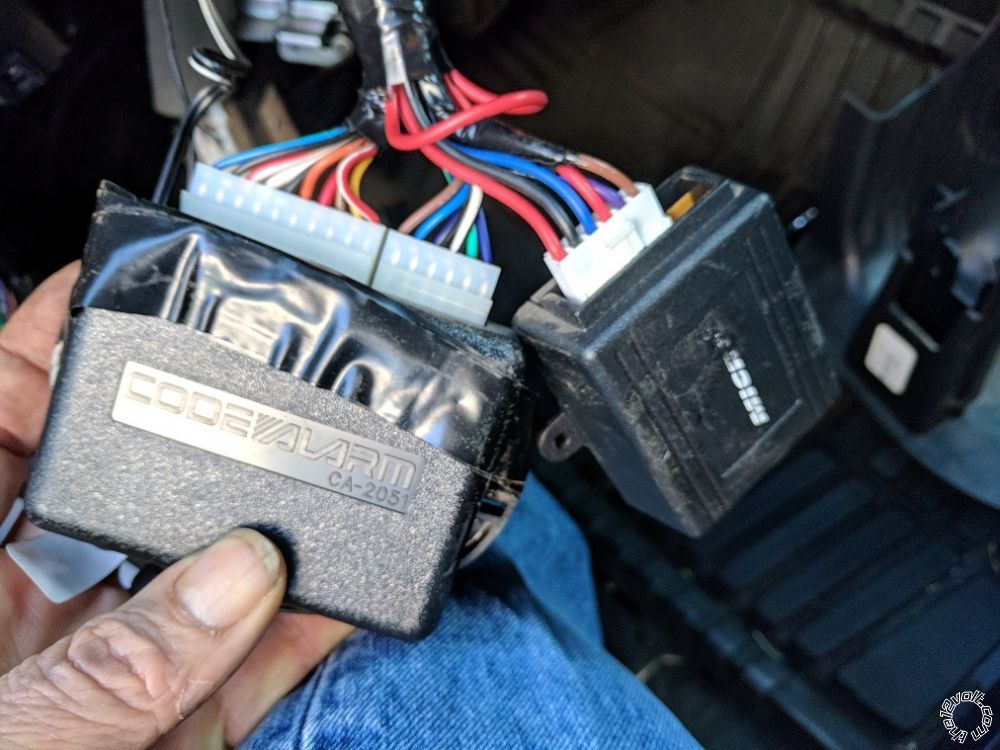
Key-less entry system is a Code-Alarm CA2051 and was professionally installed when the car was new. I'm guessing this will have to be removed and the door locks connected directly to the new system, possibly with a relay/relays? Currently all doors lock and unlock all together and I'm good with that.
rraider1 
Member - Posts: 28
Member spacespace
Joined: May 05, 2016
Location: Texas, United States
Posted: November 06, 2017 at 2:13 PM / IP Logged Link to Post Post Reply Quote rraider1
Anyone willing to look over my wiring chart for me? Still not sure how to tackle the keyless entry. I think I'm going to go ahead with the 5305 and no bypass.
Not sure how this will post, the spreadsheet can be viewed HERE
5305 Alarm/remote start     2013 Nissan Versa, No factory alarm, no immobilizer
Main Harness, White 5-pin connector     
1 BLACK (-) CHASSIS GROUND     ground
2 BROWN (+) SIREN OUTPUT     siren
3 RED (+) FUSED 12V DC CONSTANT INPUT     12volts pink (40A) + ignition switch, white 6 pin plug, pin 3
4 ORANGE (-) 500mA GWA (GROUND WHEN ARMED) OUTPUT     n/a
5 WHITE (+)/(-) SELECTABLE PARKING LIGHT OUTPUT (FUSED)     Parking Lights+ red to blue + driver kick, gray 16 pin plug, pin 4
     
Auxiliary/Shutdown/Trigger Harness, White 24-pin connector     
1 PNK/WHITE (-) 200mA IGNITION 2/ACCESSORY OUTPUT     n/a
2 BLUE/WHITE (-) 200mA 2ND STATUS /REAR DEFOGGER OUTPUT     Green rear defogger switch/HVAC control, black 15 pin plug, pin 10
3 RED/WHITE (-) 200mA TRUNK RELEASE OUTPUT     n/a
4 BLACK/YELLOW (-) 200mA DOME LIGHT OUTPUT     BLACK 15-PIN PLUG, PIN 8 @ BCM,
5 DARK BLUE (-) 200mA STATUS OUTPUT     n/a
6 WHITE/BLACK (-) 200mA AUX 5 OUTPUT     n/a
7 WHITE/VIOLET (-) 200mA 2nd UNLOCK OUTPUT     ?
8 ORANGE/BLACK (-) 200mA AUX 6 OUTPUT     
9 GRAY (-) HOOD PIN INPUT     hood pin
10 BLUE (-) TRUNK PIN/INSTANT TRIGGER INPUT     trunk pin
11 WHITE/BLUE ** (-) REMOTE START ACTIVATION INPUT     n/a
12 VIOLET/WHITE TACHOMETER INPUT     
13 BLACK/WHITE* (-) PARKING BRAKE INPUT/EMERGENCY INPUT     ground
14 GREEN/BLACK (-) 200mA FACTORY ALARM DISARM OUTPUT     n/a
15 GREEN (-) DOOR INPUT     lt. blue - BCM above driver kick, white 15 pin plug, pin 7
16 BROWN/BLACK (-) 200mA HORN HONK OUTPUT     Horn Trigger red - horn switch, gray 8 pin plug, pin 8
17 PINK (-) 200mA IGNITION 1 OUTPUT     n/a
18 VIOLET (+) DOOR INPUT     n/a
19 VIOLET/BLACK (-) 200mA AUX 4 OUTPUT     n/a
20 BROWN (+) BRAKE SHUTDOWN INPUT     lt. green or red, brake switch
21 VIOLET/YELLOW (-) 200mA STARTER OUTPUT     n/a
22 GRAY/BLACK (-) DIESEL WTS (WAIT-TO-START) INPUT     n/a
23 ORANGE (-) 200mA ACCESSORY OUTPUT     n/a
24 GREEN/WHITE (-) 200mA FACTORY ALARM ARM OUTPUT     n/a
     
Remote Start, White 10-pin heavy gauge connector     
1 No Connection     
2 RED/BLACK (+) FUSED 12V ACCESSORY/STARTER INPUT     12volts pink (40A) + ignition switch, white 6 pin plug, pin 3
3 PINK/BLACK* (+) IGNITION 2/ACCESSORY ISOLATION WIRE # 87A key side (if required) of IGNITION2/ACCESSORY     n/a
4 PINK/WHITE (+) IGNITION 2 / ACCESSORY RELAY OUTPUT     lt. blue + ignition switch, white 6 pin plug, pin 5
5 RED (+) FUSED 12V IGNITION 1 INPUT     12volts pink (40A) + ignition switch, white 6 pin plug, pin 3
6 GREEN (+) STARTER INPUT (KEY SIDE OF THE STARTER DISABLE)     Starter white + ignition switch, white 6 pin plug, pin 2
7 VIOLET (+) STARTER OUTPUT (CAR SIDE OF THE STARTER DISABLE)     Starter white + ignition switch, white 6 pin plug, pin 2
8 ORANGE (+) ACCESSORY OUTPUT     YELLOW (+) WHITE 6-PIN PLUG, PIN 4 @ IGNITION SWITCH
9 RED/WHITE (+) FUSED 12V IGNITION 2 / FLEX RELAY INPUT 87     12volts pink (40A) + ignition switch, white 6 pin plug, pin 3
10 PINK (+) IGNITION 1 INPUT/OUTPUT     Ignition gray + ignition switch, white 6 pin plug, pin 1
     
     
Door Lock, White 3-pin connector     
1 BLUE (-) 500mA UNLOCK OUTPUT     ? third party keyless entry?
2 EMPTY NOT USED     
3 GREEN (-) 500mA LOCK OUTPUT     ? third party keyless entry?
     
D2D Harness, Red 4-pin connector     
1 BLUE D2D - TX     
2 BLACK (-) GROUND     
3 GREEN D2d - RX     
4 RED (+) 12V     
     
Bitwriter/Directed SmartStart Harness, Black 3-pin connector     
1 RED (+) 12V     
2 ORANGE ESP 2 - RX/TX     
3 BLACK (+) 12V     
kreg357 
Platinum - Posts: 7,781
Platinum spaceThis member has made a donation to the12volt.com. Click here for more info.spaceThis member has been recognized as an authority in Electrical Theory. Click here for more info.spaceThis member has been recognized as an authority in Mobile Security and Convenience. Click here for more info.spacespace
Joined: January 30, 2009
Location: Pennsylvania, United States
Posted: November 06, 2017 at 8:58 PM / IP Logged Link to Post Post Reply Quote kreg357
The Lt Blue Door Pin will only give you the drivers door. To monitor all doors you will need to
connect to all the door trigger wires with diode isolation. Here is the info :
Driver's Front Door Pin    LT BLUE (-)        BCM WHITE 15 PIN CONN, PIN 7
Pass Front Door Pin        PINK (-) BCM WHITE 40 PIN CONN, PIN 12
Driver's Rear Door Pin   WHITE (-)              BCM WHITE 15 PIN CONN, PIN 8
Pass Rear Door Pin        LT GREEN (-)       BCM WHITE 40 PIN CONN, PIN 13
Here is the info on the trunk trigger wire :
Trunk Pin    PINK (-)        BCM WHITE 15 PIN CONN, PIN 2
You will need to test the Defog wire to determine if it's latched or a pulse and program the R/S accordingly.
Domelight Supervision might not be required. Test to see if an Unlock from the aftermarket
RKE system makes the domelight come on.
Remember to program the unit for ACC2 output on the Flex Relay Pink/White wire and set the Parking Light
jumper to (+).
The CA2051 system has built in relays that might be directly controlling the door lock solenoids. If
this is the case, you might need a DEI 451M module to replace it.
Other than that, all you wiring looks fine.
Soldering is fun!
rraider1 
Member - Posts: 28
Member spacespace
Joined: May 05, 2016
Location: Texas, United States
Posted: November 07, 2017 at 9:14 PM / IP Logged Link to Post Post Reply Quote rraider1
Thanks!
I went ahead and ordered a 5706v (wiring looks to be pretty much the same as above and it will match what I have in the pickup), a DEI 451M, an iDatalink ALCA, and since I'll now have three DEI systems I ordered a bitwriter as well.
howie ll 
Pot Metal - Posts: 16,466
Pot Metal spacespace
Joined: January 09, 2007
Location: United Kingdom
Posted: November 08, 2017 at 6:38 AM / IP Logged Link to Post Post Reply Quote howie ll
The idatalink part is unnecessary if the vehicle doesn't have an immobiliser, all it will do is save you time and wiring.
rraider1 
Member - Posts: 28
Member spacespace
Joined: May 05, 2016
Location: Texas, United States
Posted: November 08, 2017 at 7:15 AM / IP Logged Link to Post Post Reply Quote rraider1
howie ll wrote:
The idatalink part is unnecessary if the vehicle doesn't have an immobiliser, all it will do is save you time and wiring.
I know, but I have a lot going on at the moment so time is money and in this case worth it for me.
howie ll 
Pot Metal - Posts: 16,466
Pot Metal spacespace
Joined: January 09, 2007
Location: United Kingdom
Posted: November 08, 2017 at 7:27 AM / IP Logged Link to Post Post Reply Quote howie ll
Fair enough.
rraider1 
Member - Posts: 28
Member spacespace
Joined: May 05, 2016
Location: Texas, United States
Posted: November 10, 2017 at 5:04 PM / IP Logged Link to Post Post Reply Quote rraider1
So here is the current keyless entry system. Not sure what the second smaller box is. 2013 Nissan Versa with no immobilizer -- posted image.
rraider1 
Member - Posts: 28
Member spacespace
Joined: May 05, 2016
Location: Texas, United States
Posted: November 10, 2017 at 6:23 PM / IP Logged Link to Post Post Reply Quote rraider1
Ok, guess the smaller box is the relays that come with the aftermarket actuators. Tomorrow I'll undo all the tape and hopefully I can figure out how its all wired from there.
kreg357 
Platinum - Posts: 7,781
Platinum spaceThis member has made a donation to the12volt.com. Click here for more info.spaceThis member has been recognized as an authority in Electrical Theory. Click here for more info.spaceThis member has been recognized as an authority in Mobile Security and Convenience. Click here for more info.spacespace
Joined: January 30, 2009
Location: Pennsylvania, United States
Posted: November 10, 2017 at 6:47 PM / IP Logged Link to Post Post Reply Quote kreg357
Here is a link to the CA-2051 unit :
http://www.voxxelectronics.com/docs/common/CA2051/CA2051_IM.pdf
Soldering is fun!
Page of 3

  Printable version Printable version Post ReplyPost New Topic
You cannot post new topics in this forum
You cannot reply to topics in this forum
You cannot delete your posts in this forum
You cannot edit your posts in this forum
You cannot create polls in this forum
You cannot vote in polls in this forum

  •  
Search the12volt.com
Follow the12volt.com Follow the12volt.com on Facebook
Friday, March 29, 2024 • Copyright © 1999-2024 the12volt.com, All Rights Reserved Privacy Policy & Use of Cookies
Disclaimer: *All information on this site ( the12volt.com ) is provided "as is" without any warranty of any kind, either expressed or implied, including but not limited to fitness for a particular use. Any user assumes the entire risk as to the accuracy and use of this information. Please verify all wire colors and diagrams before applying any information.

Secured by Sectigo
the12volt.com spacer
Support the12volt.com
Top
the12volt.com spacer