This is a basic Remote Start with keyless entry Pictorial for the 2002 through 2004 Toyota Camry. This car was a basic 2004 Camry LE with the 4 cylinder engine, automatic transmission, no Factory Alarm, no Auto Headlights and no transponder based engine immobilizer. As such, this Pictorial will not include info on a bypass module and will focus on this particular car and its' specific needs.
Vehicle considerations :
1. No need for a bypass module.
2. Common Type B door locks
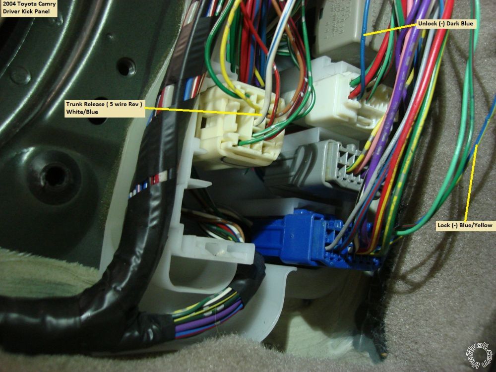
3. To duplicate the factory remotes, trunk release should be included but it is a 5 wire REV system.
4. The car has two Ignition wires, two Starter wires and one Accessory wire, necessitating an additional relay.
5. The Factory remotes are in-op while the engine is running. A R/S w/keyless entry is a good idea.
For this install a Compustar CS800-s system was chosen. There are many other systems that will handle this car, such as Prestige APS57E, Avital 4103LX, Viper 4105V and Ultra Start U1272, to name a few. Additional parts include two 10 Amp mini-relays, two inline fuse holders with 10 Amps fuses, two 1N4004 diodes and a mercury tilt switch. The mercury tilt switch is optional as you can use the R/S kit provided hood pin instead.
Please note that Bulldog Security has a great write-up on this vehicle with plenty of photos that should be reviewed and used to assist during the install. Below is a link to Bulldog Security : http://www.bulldogsecurity.com/bdnew/vehiclewiringdiagrams.aspx
Here is the CS800-s to 2004 Camry that was used :
CM800-s 2004 Camry
CN1
1 Red..................+12V Constant....................................White/Red @ Ignition Harness Pin 7
2 Green/White......+ Parking Light Out.......... ..................not used
3 Red/White........+12V Constant....................................thick Black at fuse box
4 White................+ Accessory.......................................Blue/Red @ Ignition Harness Pin3
5 Blue.................+ Selectable...set to IGN2 via jumper..Black/Yellow @ Ignition Harness Pin 4
6 Yellow.............+ Starter..............................................Black/White @ Ignition Harness Pin 8
7 Green..............+ Ignition.............................................Black/Red @ Ignition Harness Pin 6
8 Black...............Chassis Ground...................................Chassis Ground
CN2
1 Green/White.........(-) Parking Lights..............Red @ Headlight Switch connector
2 Red/Black.............(-) Starter............................to Starter2 Relay Pin 85
3 White/Black.........(-) Accessory.......................not used
4 Black....................(-) Status..............................not used
5 Orange.................(-) Rearm.............................not used
6 Orange/White.....(-) Disarm............................not used
7 White...................(-) Horn................................Green/Black @ 24 Pin connector, lower fuse box
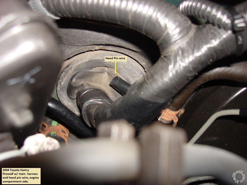
8 Gray/Black.........(-) Hood Pin.........................to mercury tilt switch
9 Lt Blue/White....(+) Brake..............................Green/White @ 20 Pin connector, lower fuse box
10 Red/White........(-) Trigger Start...................not used
11 Red........................(+) Trigger Start..................not used
12 Yellow/Black.....Tach.....................................Black/Orange @ OBD2 plug, Pin 9 *
* 4 cylinder engine only
CN3
1 Empty
2 Violet/White..........(-) Trunk Release......................to Trunk Release relay Pin 85
3 Orange/Black.......(-) Driver Priority Unlock...........not used
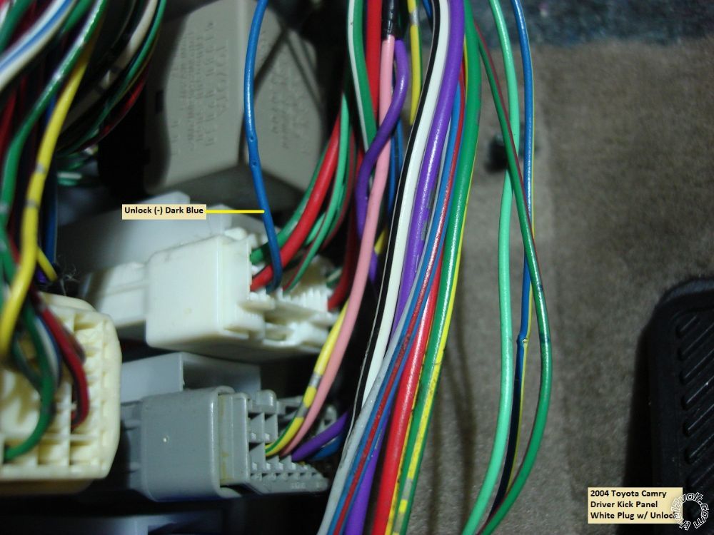
4 Blue......................(-) Unlock..................................Blue @ 20 Pin White connector in DKP **
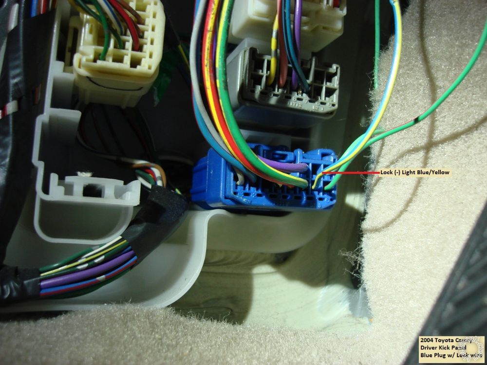
5 Blue/Black............(-) Lock......................................Blue/Yellow @ 12 Pin Blue connector in DKP
6 Empty
** You can program the CS800 for double unlock pulse to unlock all the door with one press of the remotes unlock button or leave it at single pulse and have progressive unlock.
Starter2 Relay
Pin 85 to CS800 CN2 Pin 2 Red/Black
Pin 86 and 87 to +12V Constant @ White wire at ignition connector, Pin 2 through 10 Amp fuse
Pin 30 to Black/Yellow @ Ignition Harness, Pin 1
Trunk Release Relay
Pin 85 to CS800 CN3 Pin 2 Violet/White
Pin 86 and 87 to +12V constant joined with CN1 Red going to White/Red @ Ignition Harness Pin 7 through 10 Amp fuse
Pin 87a to upper side of cut White/Blue Trunk Release wire
Pin 30 to connector side of cut White/Blue Trunk Release wire
Both relays have a 1N4004 diode across Pin 85 to Pin 86 with the band towards Pin 86.
Bench prepped R/S ready for placement and wire connections :
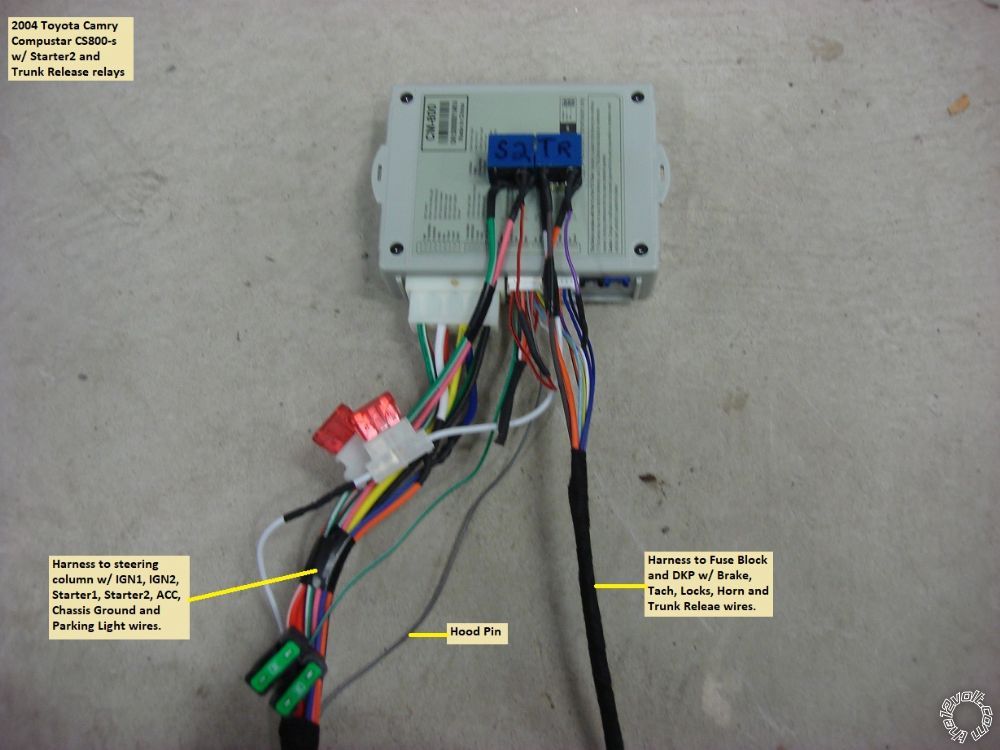
Disassembly :
Lift the leading edge of the driver side door sill panel slightly. Remove the plastic nut at the front of the Driver Kick Panel, then pull the panel towards the right.
Remove the fuse panel cover in the lower driver side dash panel and remove the sliding tray holder above. This will expose one hidden Phillips screw shown in the photo below.
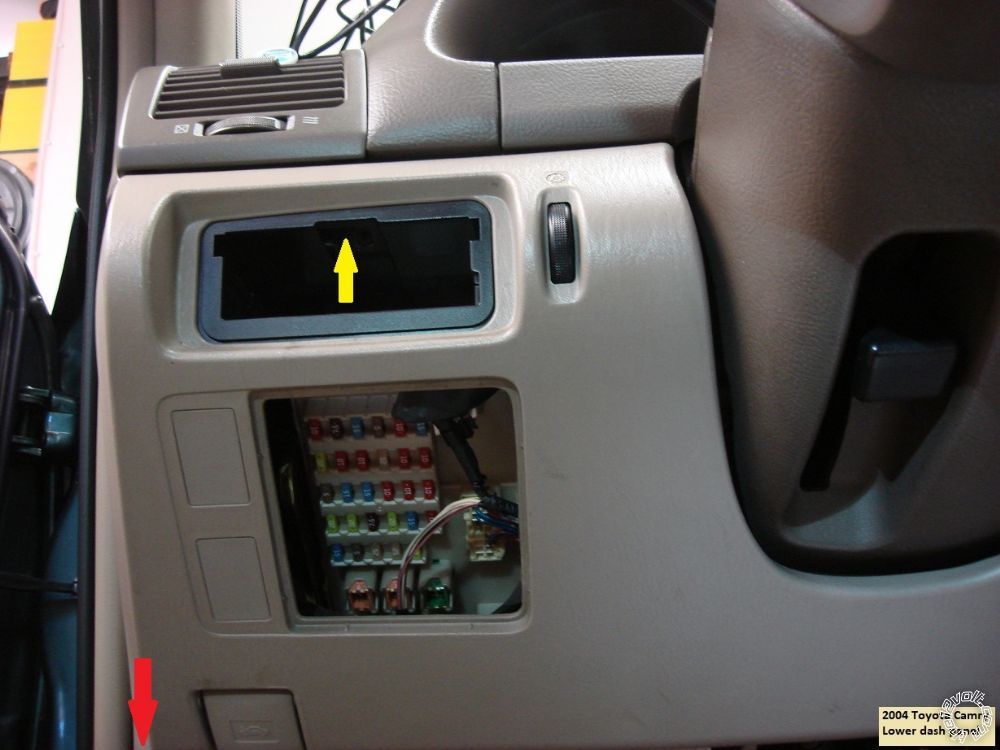
Next remove the hidden screw in the lower dash panel indicated below :
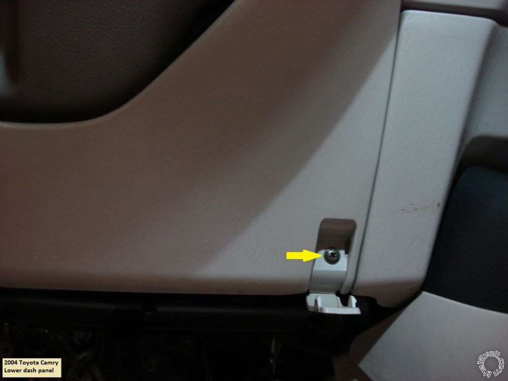
Finally remove the 10mm screw shown in the picture below :
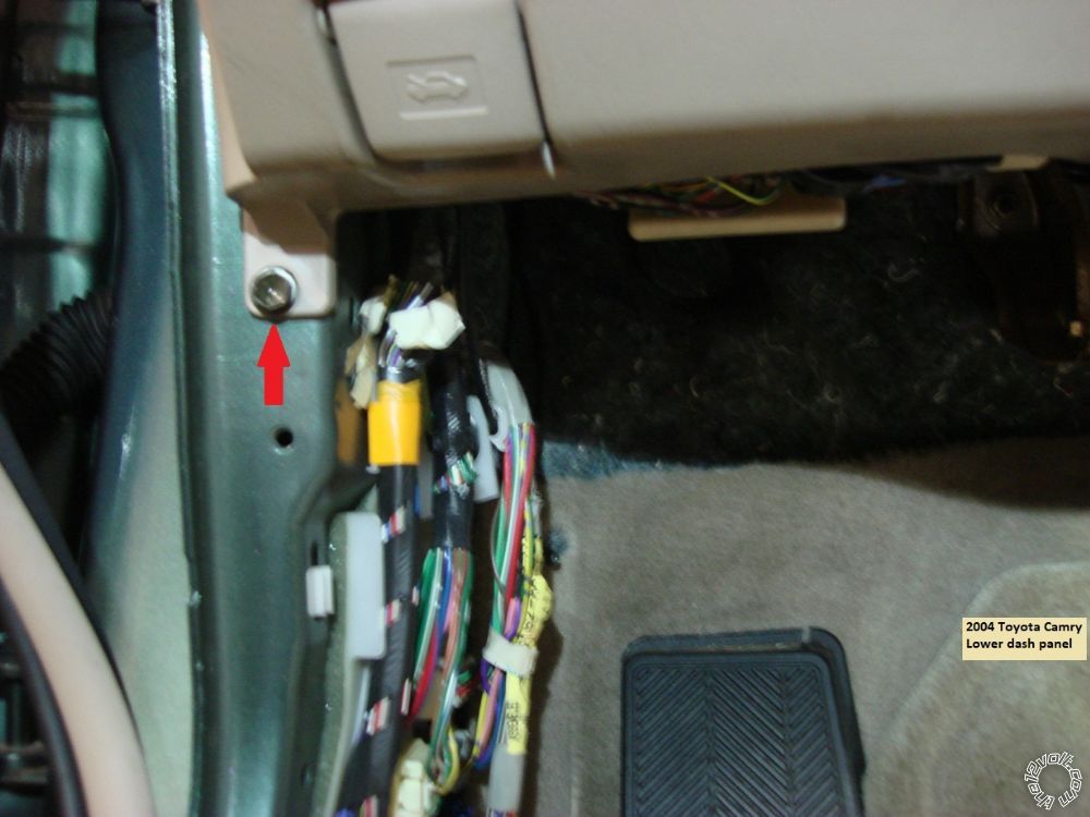
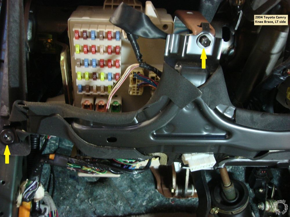
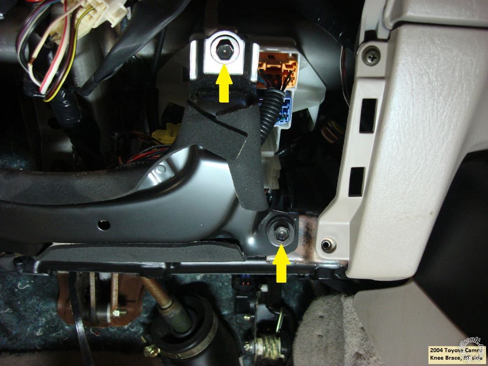
The lower dash panel can now be removed by pulling it straight back and off. This will expose the four 10mm screws shown below that retain the knee brace. The knee brace has the OBD2 plug mount. Just release the OBD2 plug and place the knee brace aside.
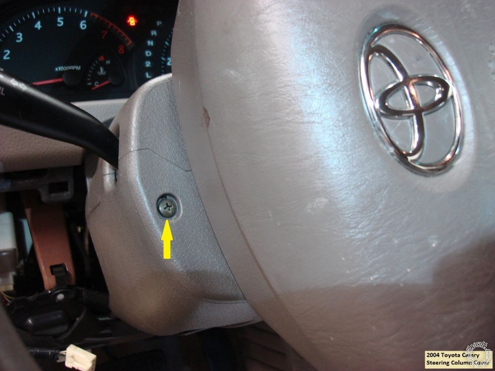
Next are the 2 Phillips screws that hold the steering column cover in place. Photo below :
Squeeze the seams to separate the lower steering column cover and remove it.
All of the necessary wires are now exposed.
Wiring :
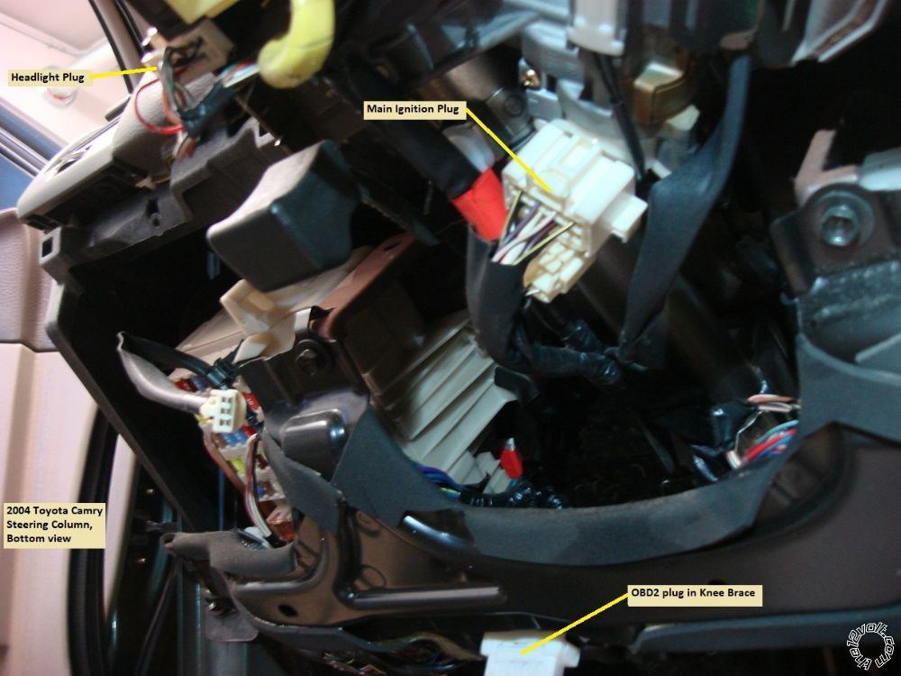
The ignition switch connector is below the ignition switch and shown in the following photo :
Next is a shot of the ignition switch with the wires numbered :
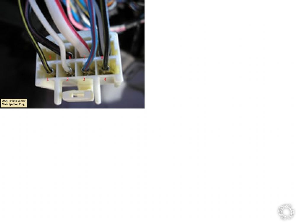
Here is a chart of those wires :
Pin 1 Starter 2..................................Black/Yellow 20 gauge
Pin 2 +12V Constant 10 Amp........White 16 gauge
Pin 3 Accessory................................Blue/Red 16 gauge
Pin 4 Ignition 2.................................Black/Yellow 20 gauge
Pin 5 Empty
Pin 6 Ignition 1.................................Black/Red 14 gauge
Pin 7 +12V Constant 12 gauge......White/Red
Pin 8 Starter 1.................................Black/White 12 gauge
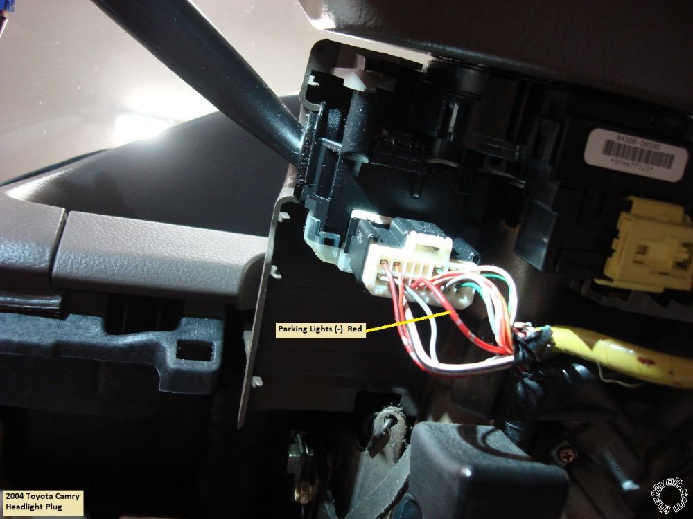
Staying at the steering column, here is a picture of the Headlight plug with the (-) Parking Light wire indicated :
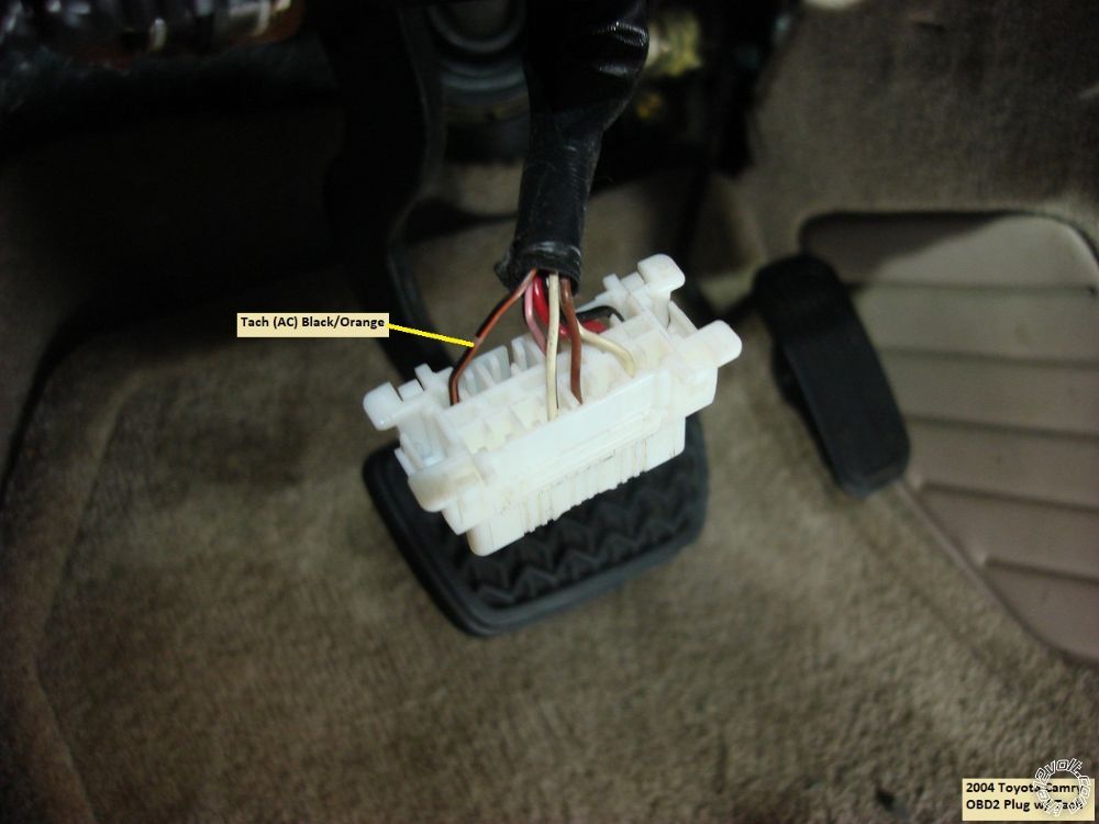
Next we move to the OBD2 plug for the Tach wire :
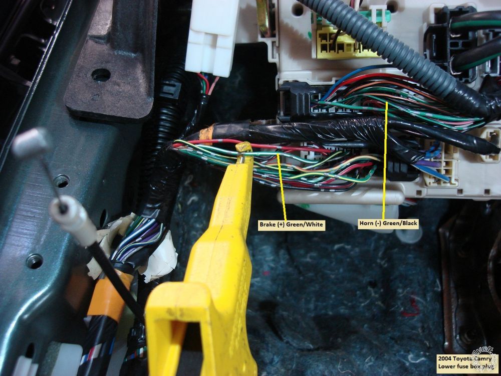
Going slightly more to the left we come to the lower fuse box plugs for the Brake and Horn wires :
And finally, at the lower Driver Kick Panel we have these wires :
Trunk Release :
Unlock wire :
Lock wire :
For the hood pin wire, firewall pass through can be had at the main harness grommet located high above the gas pedal. Here is a photo on the hood pin wire coming through that grommet on the engine side :
There are many good places to attach the Chassis Ground wire. I used a self-tapping metal screw and ran it to the heavy dash cross pipe. There is a large cavity behind the fuse box to secure the CS800-s brain.
That about does it for the wiring. There are a few programming changes that should be made to the CS800. To run in Tach Mode change Feature 2-04 to option 2. You must also do a Tach Learn. If you want all doors to unlock at once, change Feature 1-03 to option 2, double unlock pulse. Being as the car does not have a factory alarm system, you can set the trunk to release without first unlocking the doors by changing Feature 1-10 to option 3. If you need a longer R/S run time than the default 15 minutes, see Feature 1-07. Another option you might want to change is the Horn honk, Default is after a second Lock command. See Feature 2-08 for more options.
Test everything and button it up. Remember to use a Digital Multi Meter to test vehicle wires and make all the wire connections with a quality soldered joint.
Soldering is fun!
 Printable version


 Disassembly :
Lift the leading edge of the driver side door sill panel slightly. Remove the plastic nut at the front of the Driver Kick Panel, then pull the panel towards the right.
Remove the fuse panel cover in the lower driver side dash panel and remove the sliding tray holder above. This will expose one hidden Phillips screw shown in the photo below.
 Next remove the hidden screw in the lower dash panel indicated below :
 Finally remove the 10mm screw shown in the picture below :
 The lower dash panel can now be removed by pulling it straight back and off. This will expose the four 10mm screws shown below that retain the knee brace. The knee brace has the OBD2 plug mount. Just release the OBD2 plug and place the knee brace aside.

 Next are the 2 Phillips screws that hold the steering column cover in place. Photo below :
 Squeeze the seams to separate the lower steering column cover and remove it.
All of the necessary wires are now exposed.
Wiring :
The ignition switch connector is below the ignition switch and shown in the following photo :
 Next is a shot of the ignition switch with the wires numbered :
 Here is a chart of those wires :
Pin 1 Starter 2..................................Black/Yellow 20 gauge
Pin 2 +12V Constant 10 Amp........White 16 gauge
Pin 3 Accessory................................Blue/Red 16 gauge
Pin 4 Ignition 2.................................Black/Yellow 20 gauge
Pin 5 Empty
Pin 6 Ignition 1.................................Black/Red 14 gauge
Pin 7 +12V Constant 12 gauge......White/Red
Pin 8 Starter 1.................................Black/White 12 gauge
Staying at the steering column, here is a picture of the Headlight plug with the (-) Parking Light wire indicated :
 Next we move to the OBD2 plug for the Tach wire :
 Going slightly more to the left we come to the lower fuse box plugs for the Brake and Horn wires :
 And finally, at the lower Driver Kick Panel we have these wires :
Trunk Release :
 Unlock wire :
 Lock wire :
 For the hood pin wire, firewall pass through can be had at the main harness grommet located high above the gas pedal. Here is a photo on the hood pin wire coming through that grommet on the engine side :
 There are many good places to attach the Chassis Ground wire. I used a self-tapping metal screw and ran it to the heavy dash cross pipe. There is a large cavity behind the fuse box to secure the CS800-s brain.
That about does it for the wiring. There are a few programming changes that should be made to the CS800. To run in Tach Mode change Feature 2-04 to option 2. You must also do a Tach Learn. If you want all doors to unlock at once, change Feature 1-03 to option 2, double unlock pulse. Being as the car does not have a factory alarm system, you can set the trunk to release without first unlocking the doors by changing Feature 1-10 to option 3. If you need a longer R/S run time than the default 15 minutes, see Feature 1-07. Another option you might want to change is the Horn honk, Default is after a second Lock command. See Feature 2-08 for more options.
Test everything and button it up. Remember to use a Digital Multi Meter to test vehicle wires and make all the wire connections with a quality soldered joint.

 If you have the supplies available, you can use thinner gauge wire for the IGN2 and Starter2 ignition wires. Makes the soldered connection easier and provides a compact bundle of wires going to the steering column.
Good luck with the install.
