the12volt.com spacer
icon

2008 Dodge Grand Caravan, Remote Start Install


Post ReplyPost New Topic
< Prev Topic Next Topic >
kennyd. 
Copper - Posts: 56
Copper spacespace
Joined: March 30, 2012
Location: Manitoba, Canada
Posted: September 25, 2018 at 6:00 AM / IP Logged Link to Post Post Reply Quote kennyd.
No no you have been very helpful kreg. Thank you very much! Ive been searching that diver kick panel for the door lock wires, I cant find the purple and green wire. I must be blind or something, it must be there! I'll have to recheck all my connections again!
kreg357 
Platinum - Posts: 7,781
Platinum spaceThis member has made a donation to the12volt.com. Click here for more info.spaceThis member has been recognized as an authority in Electrical Theory. Click here for more info.spaceThis member has been recognized as an authority in Mobile Security and Convenience. Click here for more info.spacespace
Joined: January 30, 2009
Location: Pennsylvania, United States
Posted: September 25, 2018 at 7:14 AM / IP Logged Link to Post Post Reply Quote kreg357
Dumb question, but if the EVO-ALL handles the locks and alarm for you via its connection to the vans CAN Bus system, why do you need to locate those wires?
The EVO-ALL install guide shows all the necessary connections including the R/S units +12V power, chassis ground and Parking Lights. Other than possibly the Horn or Hood Pin, there shouldn't be any other connections needed or made to the van for this install.
Soldering is fun!
kennyd. 
Copper - Posts: 56
Copper spacespace
Joined: March 30, 2012
Location: Manitoba, Canada
Posted: September 26, 2018 at 4:45 PM / IP Logged Link to Post Post Reply Quote kennyd.
Yes your correct! Since Im having trouble finding some of the wire on the vehicle, Im going to connect all the wires back to the evo-all, My question is when I tried programming the evo-all it doesn't flash like its supposed to in the guide, so I don' t know if its programmed or not. Im going to start all over this weekend! I'll post back what Ive done Thank you for all your replies!!
kennyd. 
Copper - Posts: 56
Copper spacespace
Joined: March 30, 2012
Location: Manitoba, Canada
Posted: October 20, 2018 at 7:06 PM / IP Logged Link to Post Post Reply Quote kennyd.
hi kreg, so I just purchased the forton flashlink manager and connected tp my evoall, updated the software. I've made changes to the setting and have changed the datalink protocols to F3 D2D setting to "ON". Unfortunatly while I was following the programming steps I still do not get the Flashing BULE LED, to confirm programming was successful.
I've been double and triple checking the two CAN lines. the wiring harness from the WIN module in the fortin guide show two CAN line wires and one of wires are colored white/grey, and one white/blue. I followed the wiring diagram pictures from the Evoall to the remote start and connections to the WIN module wiring harness
I still can't seem to get passed the programming part?
In the fortin flashlink manager in the left column I selected my vehicle, installation and connection types, I selected to Standard installation and standard connection, and alarm system to No alarm system
what else should I check?
kreg357 
Platinum - Posts: 7,781
Platinum spaceThis member has made a donation to the12volt.com. Click here for more info.spaceThis member has been recognized as an authority in Electrical Theory. Click here for more info.spaceThis member has been recognized as an authority in Mobile Security and Convenience. Click here for more info.spacespace
Joined: January 30, 2009
Location: Pennsylvania, United States
Posted: October 22, 2018 at 8:21 PM / IP Logged Link to Post Post Reply Quote kreg357
All the sources I have indicate that the twisted pair CAN wires at the ignition switch node are White/Brown and White/Light Blue. Here is a diagram of the Node Connector :
2008 Dodge Grand Caravan, Remote Start Install - Page 2 -- posted image.
Double check these wires. All connections should be soldered.
Soldering is fun!
kennyd. 
Copper - Posts: 56
Copper spacespace
Joined: March 30, 2012
Location: Manitoba, Canada
Posted: October 23, 2018 at 8:04 PM / IP Logged Link to Post Post Reply Quote kennyd.
In the fortin guide Can High is whilte/grey and Can Low is white/Lt. blue? Are the fortin guides worng? Thanks very much Kreg! I will double check the node connector this week and give you an update? Here is the link from the fortin website Q&A page where I posted my problem! https://fortin.ca/en/qa/84114/evo-all-not-programming-on-08-dodge-grand-caravan?show=84114#q84114
kennyd. 
Copper - Posts: 56
Copper spacespace
Joined: March 30, 2012
Location: Manitoba, Canada
Posted: November 18, 2018 at 9:46 PM / IP Logged Link to Post Post Reply Quote kennyd.
Hi kreg, sorry for the late response, I've been buzy with work and other things!! Anyway I got started this evening and checked the two CAN wires and I had Both HIGH and LOW mixed up! Your diagram which I followed were correct and compared to the fortin installation guide the CAN wire colors were wrong. Switched the wires with the diagram you gave me and the programming procedure with the fortin evoall went flawlessly, the procedure was exactly as in the fortin guide. Door locks work perfectly!
Now I've tried remote starting with the codealarm remote remote start module clicks, the evoall LED turns Orange, but no lights on initial start on the cluster gauge? All the lights do not light up in the dash cluster?
I have the pink wire ignition 1 wire (remote start module) with yellow wire (ignition evoall) with yellow/red (COMM2 evoall) connected to pink/white to the vehicle side of the wiring harness of the WIN ignition harness.
Also 12V Battery wire (remote start module) with yellow/blue (NO2 evoall) connected to 5amp fuse connected to light blue/red 12V (WIN Module wiring harness)
Start wire (remote start module) connected to starter wire (evoall module). Everything is connected exactly like in the fortin guide. Any ideas guys?
kreg357 
Platinum - Posts: 7,781
Platinum spaceThis member has made a donation to the12volt.com. Click here for more info.spaceThis member has been recognized as an authority in Electrical Theory. Click here for more info.spaceThis member has been recognized as an authority in Mobile Security and Convenience. Click here for more info.spacespace
Joined: January 30, 2009
Location: Pennsylvania, United States
Posted: November 19, 2018 at 2:51 AM / IP Logged Link to Post Post Reply Quote kreg357
Perhaps an omission, but you did not mention the EVO-ALL Yellow/Green wire at Pin D1. On the early Grand Caravans ( 2008 - 2010 ) you must cut the mini-vans' Red/White Ignition wire and make the wire connections exactly as shown in the Install Guide #5131 Page 3 of 5. Additionally, connector and vehicle side wiring connections are critical.
Are you going D2D, using the 4 Pin data harness or W2W with the 4 Pin harness just supplying power and ground and all the other connections between the Code Alarma and EVO-ALL hardwired? If W2W, then the Starter wire connection you mentioned is needed, but in D2D mode it is handled by the D2D 4 Pin harness.
Have you programmed he Code Alarm to Tach Mode and done a successful Tach Learn?
Soldering is fun!
kennyd. 
Copper - Posts: 56
Copper spacespace
Joined: March 30, 2012
Location: Manitoba, Canada
Posted: November 19, 2018 at 6:04 PM / IP Logged Link to Post Post Reply Quote kennyd.
Oh yes I forgot to mention, the yellow/green wire (evoall) connected red/white to the ignition wring harness to the WIN. The red/white wire is cut, just like the fortin diagram. The connection is direct wire to wire soldered, NOT Data 2 Data.
The code alarm is set to tachless mode, just to see if the remote start works. Do I need to Program the tach first? Does this prevent the dash to light up when I try to remote start the vehicle?
The starter wire is connected to the start wire of the evoall.
Im following the troubleshooter from the fortin website, Im checking all of my connections of the yellow wires of the evoall, and all the wires to the start and ignition wires.
kreg357 
Platinum - Posts: 7,781
Platinum spaceThis member has made a donation to the12volt.com. Click here for more info.spaceThis member has been recognized as an authority in Electrical Theory. Click here for more info.spaceThis member has been recognized as an authority in Mobile Security and Convenience. Click here for more info.spacespace
Joined: January 30, 2009
Location: Pennsylvania, United States
Posted: November 22, 2018 at 9:40 AM / IP Logged Link to Post Post Reply Quote kreg357
Well, OK. Here goes. I am not a CodeAlarm user and was unable to find a CA5354 Install guide. Therefore this response will be not exact on the CA5354 side. That includes jumpers, options and feature programming. I believe the CA 5354 is a R/S w/Keyless entry only and has no alarm features ( siren, etc ).
It would appear that you are going in the W2W method between the CA5354 and the EVO-ALL.That is fine but does require inter-module wiring. Being as you obtained the Fortin FlashLink cable and flashed the correct firmware and made the F3 D2D option setting, you could go D2D.
Here is the needed wiring for W2W mode :
First you must cut the D2D harness from the EVO-ALL and connect the Red wire to +12V constant and the Black wire to Chassis Ground. The Blue and White wires are not used and should be insulated. When you start the EVO-ALL programming process, the EVO-ALL checks the status of the Blue and White wires and decides on D2D or W2W mode.   I would just connect the Red and Black wires to the correcponding wires of the CA5354 ( thick Red 12V and Black Chassis Ground ) near the CA5354.
In W2W mode all of the dashed lines from the R/S to the EVO-ALL must be made with a hardwire connection for all the necessary signals. These would include :
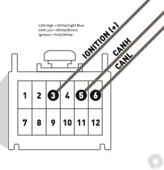
A1    Yellow           Ignition    ( has to be hardwired for both W2W and D2D ) as shown in EVO-ALL diagram
A2    Purple           Lock/Arm    to CA5354 Green Lock wire only
A3    Purple/White    Unlock/Disarm       to CA5354 Blue Unlock wire only
A8    Dark Blue       GWR           to CA5354 Start Status / Active Output (-)
A11   Black            Foor Brake to CA 5354 Brown/Red Brake (+)
A12   Pink             Tach              to CA5354 Purple/White ( optional but recommeneded to run in Tach Mode )
A15   Pink/Black   Hood Pin     to CA5354 Grey Hood Pin *
* This signal will only be present if the minivan has a Factory Alarm system and Hood Pin. If the minivan does not have a factory hood pin, you must install the CA6364 kit supplied hood pin.
It would appear that the EVO-ALL is connected to the CAN system properly being as it programmed as per the install guide. You have double checked the other vehicle wiring at the ignition node connector. I believe that the Grand Caravan has one touch starting, so the Tach signal and running in Tach Mode is not mandatory or even real important. You could just set the CA5354 to a fixed 1 second starter output if it has that optiom / feature.
Soldering is fun!
Page of 3

  Printable version Printable version Post ReplyPost New Topic
You cannot post new topics in this forum
You cannot reply to topics in this forum
You cannot delete your posts in this forum
You cannot edit your posts in this forum
You cannot create polls in this forum
You cannot vote in polls in this forum

  •  
Search the12volt.com
Follow the12volt.com Follow the12volt.com on Facebook
Thursday, March 28, 2024 • Copyright © 1999-2024 the12volt.com, All Rights Reserved Privacy Policy & Use of Cookies
Disclaimer: *All information on this site ( the12volt.com ) is provided "as is" without any warranty of any kind, either expressed or implied, including but not limited to fitness for a particular use. Any user assumes the entire risk as to the accuracy and use of this information. Please verify all wire colors and diagrams before applying any information.

Secured by Sectigo
the12volt.com spacer
Support the12volt.com
Top
the12volt.com spacer