the12volt.com spacer
icon

2015-2018 Ford Transit Remote Start Pictorial


Post ReplyPost New Topic
< Prev Topic Next Topic >
ace_boy2099 
Copper - Posts: 81
Copper spacespace
Joined: January 13, 2010
Location: Florida, United States
Posted: December 24, 2020 at 9:15 PM / IP Logged Link to Post Post Reply Quote ace_boy2099
I'm not sure if I should start a new topic or just ask here, Since it's fitting here I'll just ask here.
I see mentioned about using 3A diodes to separate the Parking light wires (since Fords geniuses decided to split them), What diodes were used? I have some 1n4001 (I think that's the number, I didn't look before asking this) but i believe they are 1 amp, What's the number for the 3amp ones? Is it the 1N5401?
I'm actually asking for the Directed Nite-Lite 545T Module install, So I'll probably need 2 for parking lights and 2 for headlights since it appears they are also separated.
Since I didn't find one when I searched the almighty Google I probably should do a write-up on how-to install it, But I'm fairly sure I'm just gonna try and get it done since I have limited time available to do things.
kreg357 
Platinum - Posts: 7,802
Platinum spaceThis member has made a donation to the12volt.com. Click here for more info.spaceThis member has been recognized as an authority in Electrical Theory. Click here for more info.spaceThis member has been recognized as an authority in Mobile Security and Convenience. Click here for more info.spacespace
Joined: January 30, 2009
Location: Pennsylvania, United States
Posted: December 25, 2020 at 6:27 AM / IP Logged Link to Post Post Reply Quote kreg357
The 1N540x series are the correct 3 Amp diodes. I usually get 1N5401's figuring that there never should be any pulses over 100 volts on these type of circuits.
You could even use the 6A10 6 Amp diodes. The price is sometimes less and the extra current capability won't hurt anything.   They are a bit bigger in diameter so larger heatshrink tube is needed.
Soldering is fun!
mustyk@att.net 
Copper - Posts: 132
Copper spacespace
Joined: November 25, 2009
Location: Michigan, United States
Posted: December 25, 2020 at 7:43 AM / IP Logged Link to Post Post Reply Quote mustyk@att.net
ace_boy_2099:
After posting that wiring diagram I didn't include the size of diode used, I am so used to just grabbing the ones I always use for that vehicle. They are 1N5406 and carry at least 3 amps which is more than enough to be safe. I got mine from "Micro Alarm" company out of California . You can also use: 1N5822.
thetopinstaller
ace_boy2099 
Copper - Posts: 81
Copper spacespace
Joined: January 13, 2010
Location: Florida, United States
Posted: December 26, 2020 at 7:18 PM / IP Logged Link to Post Post Reply Quote ace_boy2099
Today I spent half the day looking for which wires do what on my new to me 2017 Ford Transit 150, (I also discovered that there's no pats ring on mine) and found some discrepancies from the chart posted in the wiring diagram page (Listed under 2015 I believe). I don't know if anyone else has discovered this or not but I will share what I found.
I started with a Multi-Meter but then switched to my Power Probe III, easier to understand/read in my opinion. A "Short Cut" I did while testing with the power probe is once I found one of the wires I was looking for by Probing each one with the headlight switch turned on, when I found a wire that was hot I turned the switch off to verify the correct functioning, after I verified it was the correct wire I back-fed it with the power probe with the switch off to see which side it belonged to, same thing with the parking lights.
First the BCM/Fuse panel referenced for the wires has 4 plugs on it, molded into the casing body by the connectors it has "C1 Black", "C2 Brown", "C3 Brown", & "C4 Blue" and the diagram page only has "plug B" and "Plug C" which is inaccurate and for me confusing to try and decipher.
Second the category for Headlight on it is actually the high beams (It does have the note for that by the wires but it should be on it's own line not under headlights.
The actual Headlight wires (on my application/vehicle) were C2-Blue/Green (Right side/Passengers), and C3-Brown/Blue (Left side/Drivers)
when I tested the parking lights I discovered that C2-Green/Orange was both the drivers (Left) Front AND Rear, and C3-Brown/Yellow was both Passengers (right) Front AND Rear. I didn't think to test the turn signal switch once I found those wires to see if it was the turn signal wires or the park wires, but my dad said it was the running lights when I back-fed them and he looked, but I doubt he would have mistaken that.
and as for the Wipers that was C3-White. I don't recall the operation, I think it was powered while off and grounded when activated, But don't quote me on that.
If I recall correctly the parking lights and headlights read ground until power was applied to turn them on (I know the head lights (low beams) did, I made note of it). I don't remember how the high beams acted.
I did not go and double check the whole diagram on the site for accuracy but I did for the wires I was looking for. Now that I have more of an idea of where what wires are, after I get the rest of what I need, I can go in and try to install everything at once, in-fact I'm thinking of adding a remote start kit from 12volt solutions (or Compustar CM7000) to the mix too. However If one of you guys (Musty / Kreg) want to come down to Florida and do it for me, I won't object... lol, I've about had it just trying to find the wires, I'm dreading having to go in and connect to all those TINY wires in that confined space.
Edit:
I was looking at the install instructions for the Compustar CM7000 and I see in the options there's an option to turn off the security features, I'm sure it's dumb to get it and only install half of it just for remote start when I could just get the 7300 (I think, Maybe it's the 7200, Either way...)unit instead. Question on this is what all would I HAVE to hook up just to have the remote start work using the factory Keyfob (hooked to the horn wire, I forget what they call it "Trigger Input" I think), or should I just bite the bullet and do the whole alarm and starter then in the future it's just a simple option change to have the full system going? and should I get the AL Blade (Bypass, but not used as a bypass) thing for the doors and such or would this unit handle them, I'd seen a note about using PIC wires for the N.C. Wires in place of diodes and relays and such towards the end of the booklet...
kreg357 
Platinum - Posts: 7,802
Platinum spaceThis member has made a donation to the12volt.com. Click here for more info.spaceThis member has been recognized as an authority in Electrical Theory. Click here for more info.spaceThis member has been recognized as an authority in Mobile Security and Convenience. Click here for more info.spacespace
Joined: January 30, 2009
Location: Pennsylvania, United States
Posted: December 27, 2020 at 10:49 AM / IP Logged Link to Post Post Reply Quote kreg357
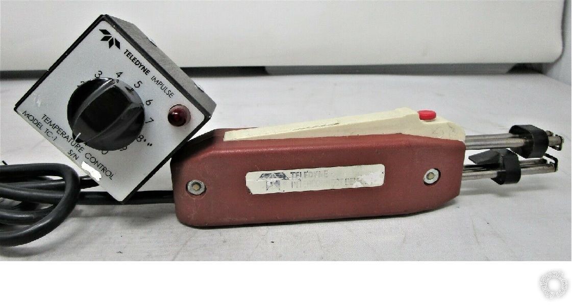
Just a tip / personal preference on my part. Considering how thin gauge the wires are in the newer vehicles, I purchased a used Teledyne StripAll Model TWC-1. New units go for $400 plus but used ones can be found for under $100. They use a pair of heated blades to melt through the wire insulation without cutting or even nicking the stranded wires. While they are meant to remove the insulation from a cut end of wire, they can be used in the middle of a length of wire. You will notice the bunched insulation on the stripped wires in this pictorial. There is an adjustable thermostat to set the blade temperature. This comes in handy for the different types of insulation material ( plastic, rubber, Teflon, etc ). The only downside is the length of the stripper arms and the width of the body. Getting in to tight places is not impossible but does take patience. Picture below :
2015-2018 Ford Transit Remote Start Pictorial - Page 3 - Last Post -- posted image.
Soldering is fun!
mustyk@att.net 
Copper - Posts: 132
Copper spacespace
Joined: November 25, 2009
Location: Michigan, United States
Posted: December 30, 2020 at 6:03 AM / IP Logged Link to Post Post Reply Quote mustyk@att.net
To: Ace_boy:
First of all you will not find a parking light wire at the headlight switch. It is a low level data bus line that is neither (+) or (-). This is why you must got to each and every one of the Parking light outputs to the bulbs (4). Secondly there are some variances to the parking light wires, I have them indicated with a star in my chart (downloads section of this site) .Example LF prkg LT wire is Green/Orange for 2015 and 2018, but may be Green/Red for 2016-2017. There may be some variances even to that. If the wire harness company ran out of Green/Orange they may have substituted Green/Red. This chart may not be Gospel but its pretty darn accurate considering I have done hundreds of these vans and this is what I have encountered. See the downloads section I have sent a couple of updated wiring Diagram charts. My wiring diagrams are color coded charts. Good Luck!
thetopinstaller
ace_boy2099 
Copper - Posts: 81
Copper spacespace
Joined: January 13, 2010
Location: Florida, United States
Posted: December 30, 2020 at 7:00 AM / IP Logged Link to Post Post Reply Quote ace_boy2099
Yeah, I noticed the headlight switch only has 4 wires so I figured that was a bust. I tested ALL of the wires in the 2 brown connectors (C2 and C3 According to the molded BCM, again not checking for all functions just the ones I was looking for at the time; Now that I decided to add a CM7000 to the mix I will have to go through again to verify the wires I didn't do the first time around. Maybe Mines made somewhat special, I don't know, I'm just reporting what I found on my vehicle and how I found it. also a little update, we figured out through a VIN decoder (on one of the ford forums, FTE i think it was, that the van is actually a Transit 350, not the 150 we originally thought. Probably doesn't matter but hey, It's worth mentioning.
ace_boy2099 
Copper - Posts: 81
Copper spacespace
Joined: January 13, 2010
Location: Florida, United States
Posted: January 06, 2021 at 3:42 PM / IP Logged Link to Post Post Reply Quote ace_boy2099
Our of curiosity, how would I tell if I can use the low power option on the cm7000, and if I can do I need the low power cn1, or just the cn 3 I think it is? I'm sure itd be alot easier to connect thin to thin than thin to thick wires.
Page of 3

If you wish to post a reply to this topic, you must first login.
If you are not already registered, you must first register.

  Printable version Printable version Post ReplyPost New Topic
You cannot post new topics in this forum
You cannot reply to topics in this forum
You cannot delete your posts in this forum
You cannot edit your posts in this forum
You cannot create polls in this forum
You cannot vote in polls in this forum

  •  
Search the12volt.com
Follow the12volt.com Follow the12volt.com on Facebook
Thursday, October 10, 2024 • Copyright © 1999-2024 the12volt.com, All Rights Reserved Privacy Policy & Use of Cookies
Disclaimer: *All information on this site ( the12volt.com ) is provided "as is" without any warranty of any kind, either expressed or implied, including but not limited to fitness for a particular use. Any user assumes the entire risk as to the accuracy and use of this information. Please verify all wire colors and diagrams before applying any information.

Secured by Sectigo
the12volt.com spacer
Support the12volt.com
Top
the12volt.com spacer