


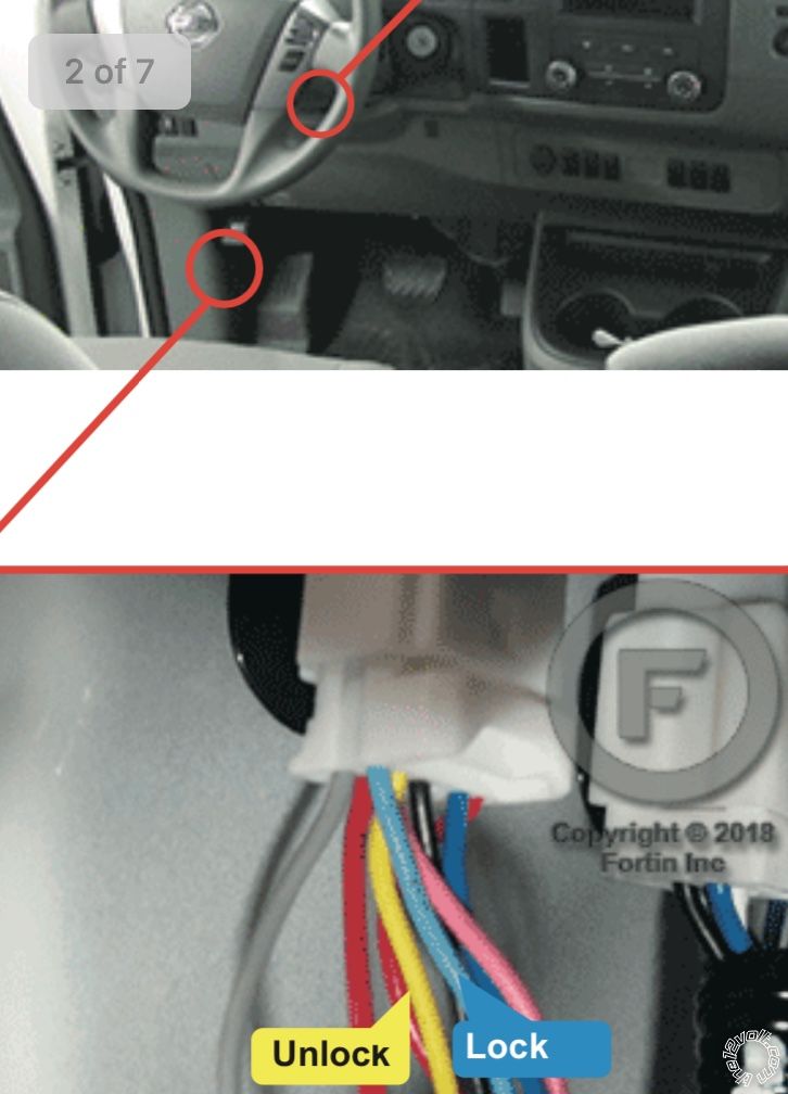
 Heres the install guide I was referencing.
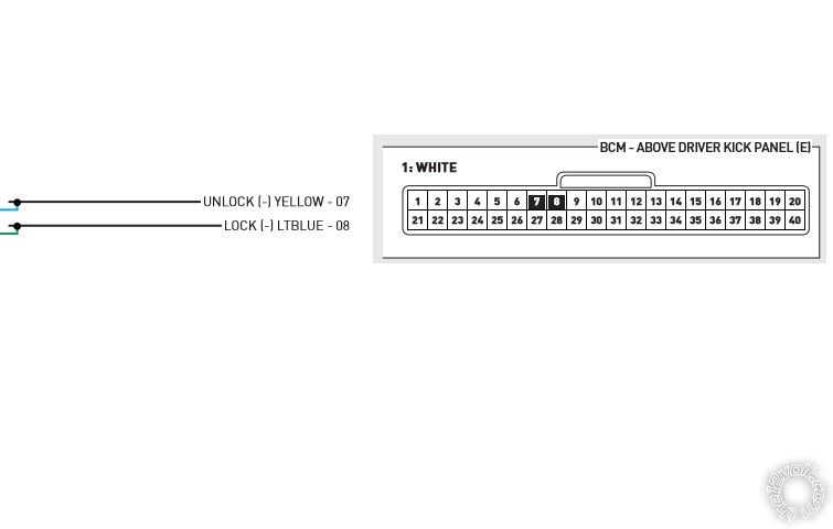 The Light Blue and Yellow wire info matches with the Bulldog, Omega and even DEI's DS4+
info for the Lock/Arm and Unlock/Disarm wires coming from the drivers door lock cylinder.
These conflicts might be due to model year or NV1500/NV2500/NV3500 body styles. The
good news is that they appear consistent with BCM, White 40 Pin connector and Pins 7 & 8.
Even the BCM location varies from "behind the instrument cluster" to "upper driver kick
panel" area.
The Light Blue and Yellow wire info matches with the Bulldog, Omega and even DEI's DS4+
info for the Lock/Arm and Unlock/Disarm wires coming from the drivers door lock cylinder.
These conflicts might be due to model year or NV1500/NV2500/NV3500 body styles. The
good news is that they appear consistent with BCM, White 40 Pin connector and Pins 7 & 8.
Even the BCM location varies from "behind the instrument cluster" to "upper driver kick
panel" area. 
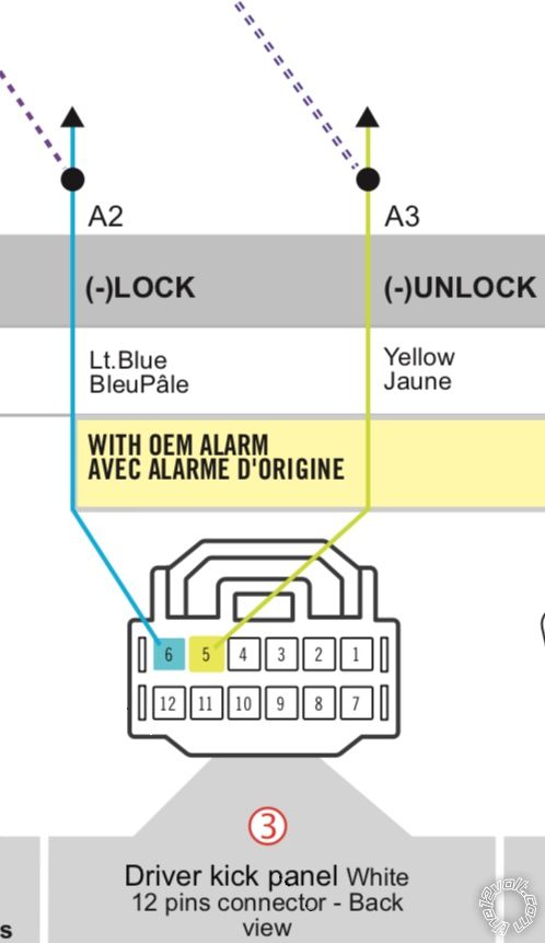
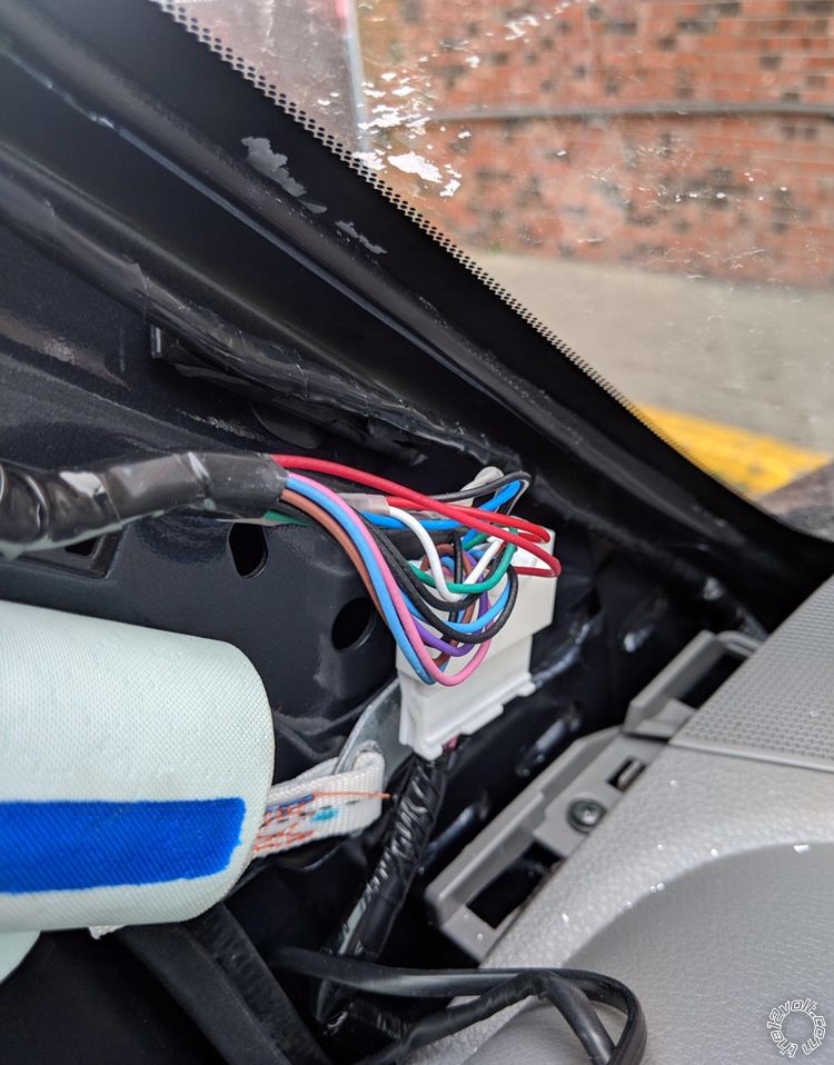

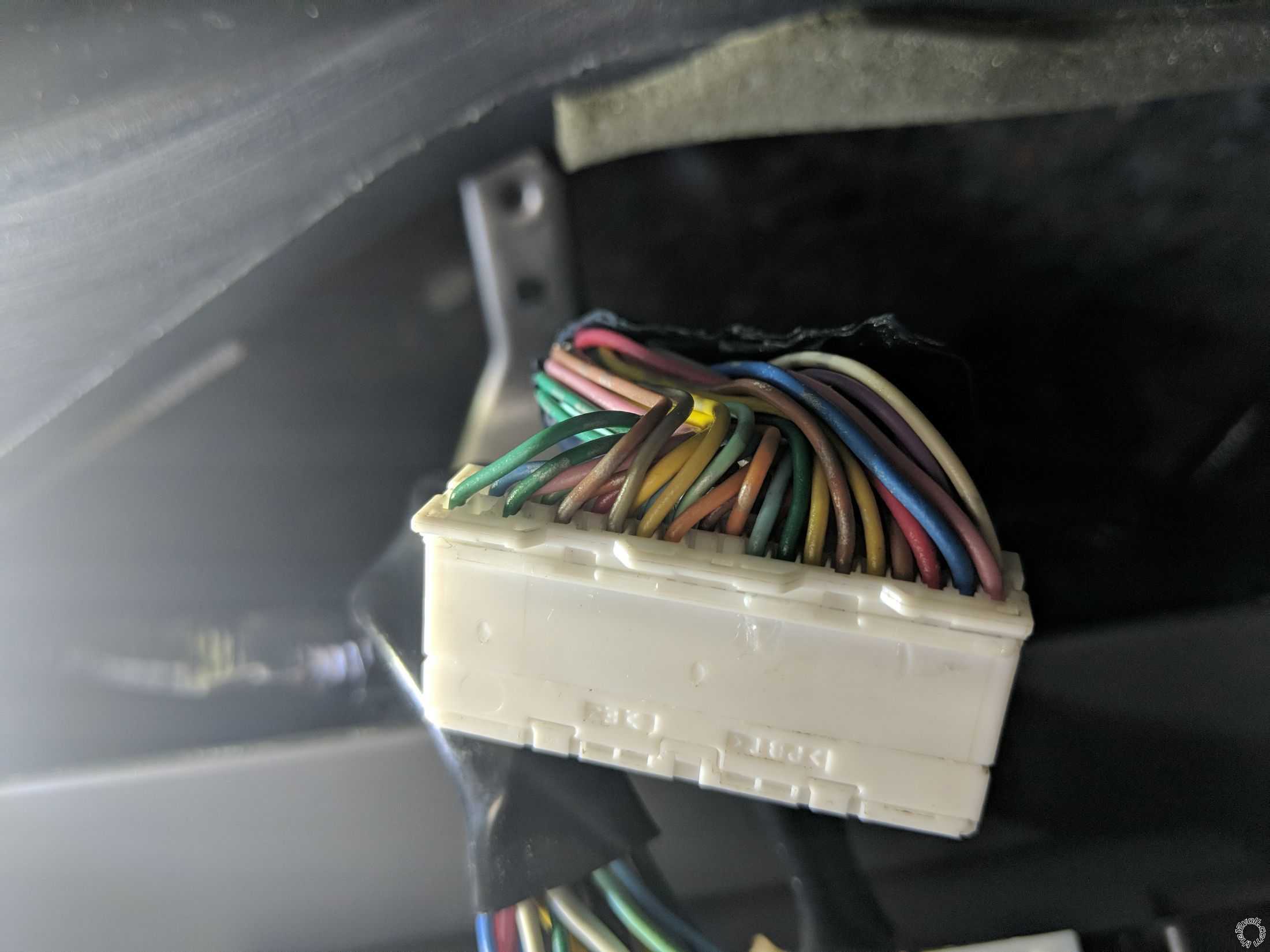
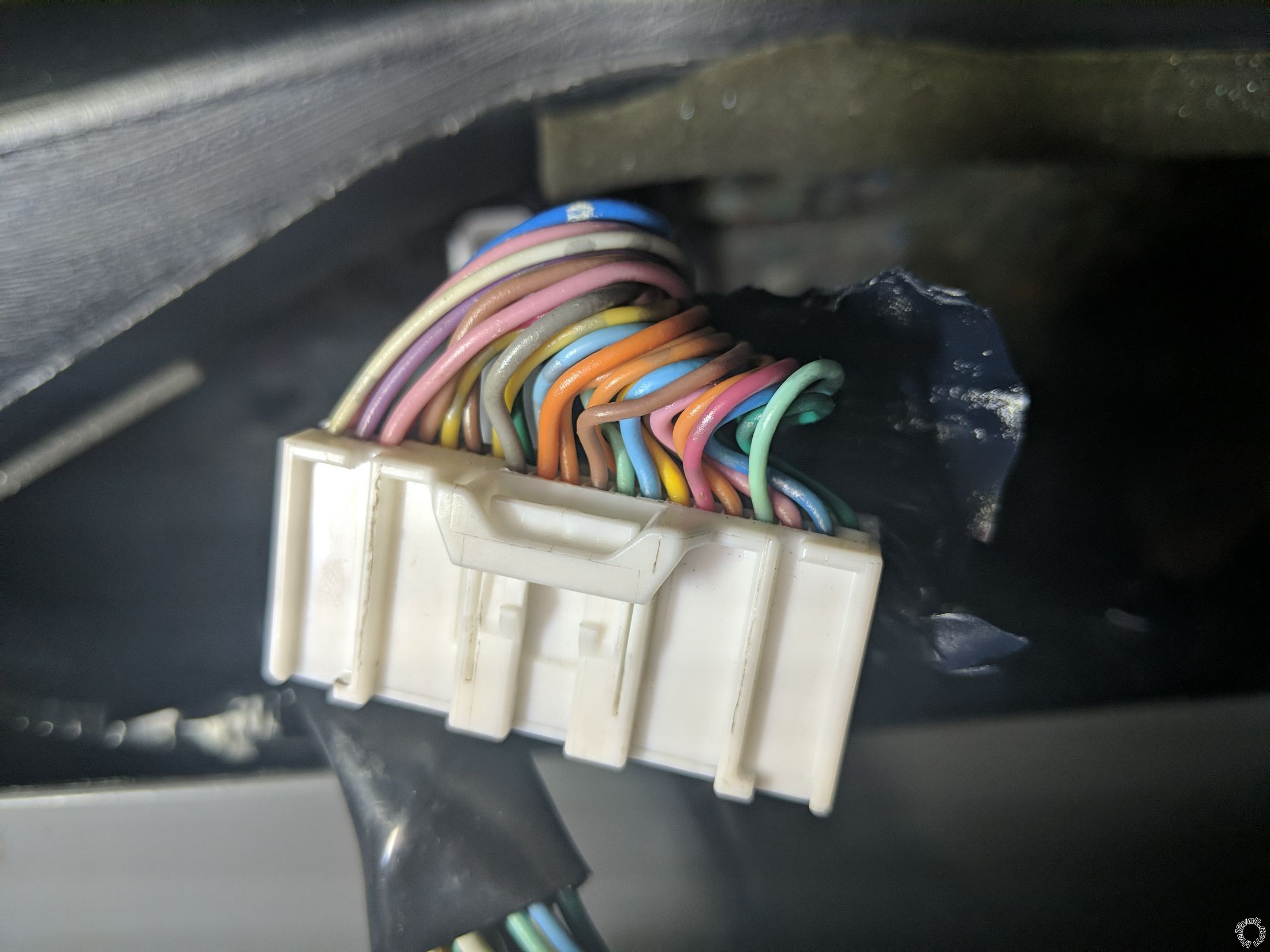 Above are two pictures (both sides) of my 40-pin BCM connector.
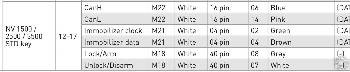
I was so intent on using Fortin and Wirecolor for my wire locations (they are much more comprehensive than iData), that I completely forgot about iData's chart that shows CanH, CanL, Immobilizer clock, Immobilizer data, Lock/Arm, Unlock/Disarm. Thank you iskidoo for reminding me.
However, the colors do not seem to match up with iData's install guide (as you can see in the picture). They do match up with Wirecolor. However, Wirecolor does not show the lock/unlock wire positions on the BCM connector. It does show pin 26 is Security LED, which should be cut. Is that applicable to my install?
I am getting ready to test the wires as kreg357 instructed. Does anyone see anything that I am missing?
Thank you again!
Above are two pictures (both sides) of my 40-pin BCM connector.
I was so intent on using Fortin and Wirecolor for my wire locations (they are much more comprehensive than iData), that I completely forgot about iData's chart that shows CanH, CanL, Immobilizer clock, Immobilizer data, Lock/Arm, Unlock/Disarm. Thank you iskidoo for reminding me.
However, the colors do not seem to match up with iData's install guide (as you can see in the picture). They do match up with Wirecolor. However, Wirecolor does not show the lock/unlock wire positions on the BCM connector. It does show pin 26 is Security LED, which should be cut. Is that applicable to my install?
I am getting ready to test the wires as kreg357 instructed. Does anyone see anything that I am missing?
Thank you again! Printable version


| You cannot post new topics in this forum You cannot reply to topics in this forum You cannot delete your posts in this forum You cannot edit your posts in this forum You cannot create polls in this forum You cannot vote in polls in this forum |

| Search the12volt.com |
Follow the12volt.com 
Monday, May 11, 2026 • Copyright © 1999-2026 the12volt.com, All Rights Reserved • Privacy Policy & Use of Cookies

Monday, May 11, 2026 • Copyright © 1999-2026 the12volt.com, All Rights Reserved • Privacy Policy & Use of Cookies
Disclaimer:
*All information on this site ( the12volt.com ) is provided "as is" without any warranty of any kind, either expressed or implied, including but not limited to fitness for a particular use. Any user assumes the entire risk as to the accuracy and use of this information. Please
verify all wire colors and diagrams before applying any information.
