the12volt.com spacer
icon

BMW E39 Remote Starter Wiring Confusion


Post ReplyPost New Topic
< Prev Topic Next Topic >
bmwe39528i1998 
Member - Posts: 31
Member spacespace
Joined: October 28, 2019
Location: Alberta, Canada
Posted: November 01, 2019 at 11:29 AM / IP Logged Link to Post Post Reply Quote bmwe39528i1998
I guess it's time to exchange the module...How unlucky can I get, getting a bad module on the first try lol.
Is the module paired to the antenna?
Just to know if I only need to exchange the module separately and can keep the antenna I already mounted?
How would you power 3 ignition wires separately? There is only one output wire from the module (yellow wire). I could repurpose the 5th relay wire by placing the pin in the middle. Thay way I would have 2nd ignition output.
But what about the 3rd wire then?
geepherder 
Platinum - Posts: 3,668
Platinum spaceThis member consistently provides reliable informationspace
Joined: October 27, 2003
Posted: November 01, 2019 at 4:54 PM / IP Logged Link to Post Post Reply Quote geepherder
The white wire (pin 10) should show a ground while remote start is running. Touch your red meter lead to a positive 12 volt source and your black meter lead to this wire. If your meter reads 12 volts during remote start, you should be able to use this wire for the parking light relay. That would still give you visual confirmation.
You should be able to swap modules. I've never used that brand, but don't see why not.
As far as powering the second ignition wire, yes, use the green wire ensuring the jumper is in the right place. The third wire will require a separate relay, triggered by the negative ignition output wire (yellow/white in the 3 pin harness).
My ex once told me I have a perfect face for radio.
bmwe39528i1998 
Member - Posts: 31
Member spacespace
Joined: October 28, 2019
Location: Alberta, Canada
Posted: November 02, 2019 at 12:38 AM / IP Logged Link to Post Post Reply Quote bmwe39528i1998
Thanks for your help.
I exchanged the modules and was finally successful.
The guy didn't think the module was to blame but still exchanged it.
Instantly everything worked right.
Powered the relay with the yellow wire, parking lights worked right away as they should.
I programmed the car to run for 25 minutes instead of 15 :)
I set the jumper to ignition and connected one of the 3 wires separately with the 2nd ignition from the remote module.
Now I only have 2 ignition wires connected together with the remote module wire.
For the 3rd wire and relay I'm not sure I understand you.
Are you talking about this 3 pin?
BMW E39 Remote Starter Wiring Confusion - Page 3 - Last Post -- posted image.
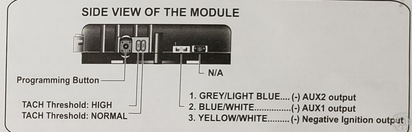
What's my connection setup with the relay. Do I put terminals 30 and 87a between the ignition wire going to the ignition switch, use yellow/white wire for ground and tap another ignition wire for positive?
Now the only thing I wanna do before putting everything back together is somehow activate the heated seats and steering wheel.
I still have a bunch of wires on the 12 pin connector. I only used 1 for trunk. But looks like they're all negative.
I'm thinking what I can use to activate it. I don't know if it needs a constant power or just a pulse to turn it on.
I need to think of some kind of a signal that activates the switch and then disengages the power.
This is a special case compared to all the wiring I did. It needs to be activated and then it works for a while before it shuts off and needs to be activated again. Kinda like the starter
geepherder 
Platinum - Posts: 3,668
Platinum spaceThis member consistently provides reliable informationspace
Joined: October 27, 2003
Posted: November 02, 2019 at 4:30 AM / IP Logged Link to Post Post Reply Quote geepherder
For the third ignition wire, yes, that negative wire in the 3 pin harness will go to 85 of a relay. 86 and 30 will connect to a constant 12 volt positive source. 87 (not 87A) will connect to the third ignition wire.
For the seats, you'll need to prove around with your meter and see what kind of signal is needed and go from there.
My ex once told me I have a perfect face for radio.
bmwe39528i1998 
Member - Posts: 31
Member spacespace
Joined: October 28, 2019
Location: Alberta, Canada
Posted: November 02, 2019 at 10:01 PM / IP Logged Link to Post Post Reply Quote bmwe39528i1998
I took my panel apart and cut off the connector with the switch to test it.
Not quite sure how it works though.
I tried testing resistance between all the wires while pressing the button but wasn't able to figure out which wires activate the button.
I found this picture online
BMW E39 Remote Starter Wiring Confusion - Page 3 - Last Post -- posted image.
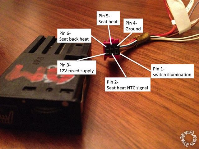
Everything is the same on my connector except mine doesnt have rear heated seats.
Once I removed the connector, I used 12 volts wall charger to supply pin 3 with power, and the light on the button came on.
So I'm thinking that when I press the button in my car, the circuit closes and the seats are heated for some time. After a while they're programmed to turn off so the power gets shut off.
I figure in this case I simply need to provide continuous power to pin 3 and it would activate the heating.
I'm not sure what pin 2 is for.
But I would've expected to have unlimited resistance between ground and power wires that went to 0 once I pressed the button.
If I can't figure it out, maybe I would connect directly to the heater connector under the seat and add an extra switch to turn it off once I'm inside the car after in warmed up.
geepherder 
Platinum - Posts: 3,668
Platinum spaceThis member consistently provides reliable informationspace
Joined: October 27, 2003
Posted: November 03, 2019 at 6:14 AM / IP Logged Link to Post Post Reply Quote geepherder
Rather than testing for resistance with it disconnected from the vehicle, I'd test for voltage in the vehicle while it's powered on. Backprobe each wire and test from a known reference (either ground or 12 volts positive).
Get a baseline without any buttons pressed, and make note of your readings. Then test while pressing a button. Repeat this for remaining buttons if you have more than one.
My ex once told me I have a perfect face for radio.
bmwe39528i1998 
Member - Posts: 31
Member spacespace
Joined: October 28, 2019
Location: Alberta, Canada
Posted: November 03, 2019 at 1:15 PM / IP Logged Link to Post Post Reply Quote bmwe39528i1998
Good thinking! This worked.
I connected multimeter negative probe to the ground wire on the connector and then tested all the wires with button off and on.
The only difference was on pin 5 wire (heat seat).
It went from 0 to 12 volts.
Now pin #3 always had 12 volts and 2 other pins had 3.5 and 5 volts.
So I guess when I press the button, 12 volts from pin 3 get transferred to pin 5.
Maybe I can put a relay in between pin 3 and pin 5 and activate it by wire 10 from my remote or by negative ignition output?
I'm trying to think of a way that I can still use the button to turn off/on the seat heat.
geepherder 
Platinum - Posts: 3,668
Platinum spaceThis member consistently provides reliable informationspace
Joined: October 27, 2003
Posted: November 03, 2019 at 8:39 PM / IP Logged Link to Post Post Reply Quote geepherder
When you release the button, does pin 5 go back to 0 volts, or does it stay at 12 volts? This will tell you whether you need a momentary or a latched output from the remote start unit.
In order to connect pins 3 and 5, one will connect to 87 and the other to 30. 12 volts constant connects to 86 and 85 to your negative aux output. Be sure to program accordingly (pulsed or latched).
My ex once told me I have a perfect face for radio.
bmwe39528i1998 
Member - Posts: 31
Member spacespace
Joined: October 28, 2019
Location: Alberta, Canada
Posted: November 03, 2019 at 10:06 PM / IP Logged Link to Post Post Reply Quote bmwe39528i1998
When I click it once, it lights up and stays on with 12 volts. If I press it again, it turns off and goes to 0 volts. Actually I'm not even sure if it turns off automatically or not, I can't remember.
I'm actually not sure if that means I should program it as latched or pulsed. I guess latched so that the relay closes and the supply of power is continuous.
I figure I can take constant 12 volts from pim 3 wire?
I'm going to try this tomorrow and report back to supply terminal 85 or 86.
I will try to incorporate rear defrost as well.
Page of 3

If you wish to post a reply to this topic, you must first login.
If you are not already registered, you must first register.

  Printable version Printable version Post ReplyPost New Topic
You cannot post new topics in this forum
You cannot reply to topics in this forum
You cannot delete your posts in this forum
You cannot edit your posts in this forum
You cannot create polls in this forum
You cannot vote in polls in this forum

  •  
Search the12volt.com
Follow the12volt.com Follow the12volt.com on Facebook
Tuesday, April 30, 2024 • Copyright © 1999-2024 the12volt.com, All Rights Reserved Privacy Policy & Use of Cookies
Disclaimer: *All information on this site ( the12volt.com ) is provided "as is" without any warranty of any kind, either expressed or implied, including but not limited to fitness for a particular use. Any user assumes the entire risk as to the accuracy and use of this information. Please verify all wire colors and diagrams before applying any information.

Secured by Sectigo
the12volt.com spacer
Support the12volt.com
Top
the12volt.com spacer