This is my ignition switch pinout
Pin
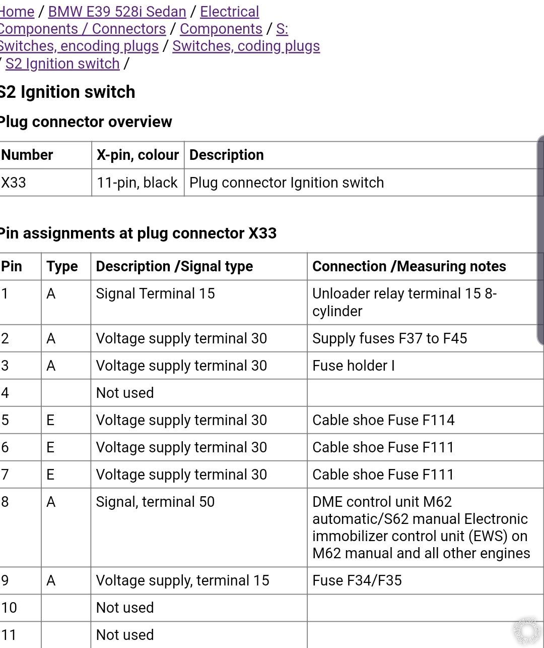
Differences:
I've got nothing on pin 9, though the picture says "voltage supply"
I've got a green wire on pin 10, while it's empty on the picture.
I don't know why it's different.
None of them seem to match up exactly to mine
https://www.newtis.info/tisv2/a/en/e39-528i-lim/components-connectors/components/f-fuses/fuses/f35-fuse/q-S2
None of them say which wire is ignition, accessory etc.
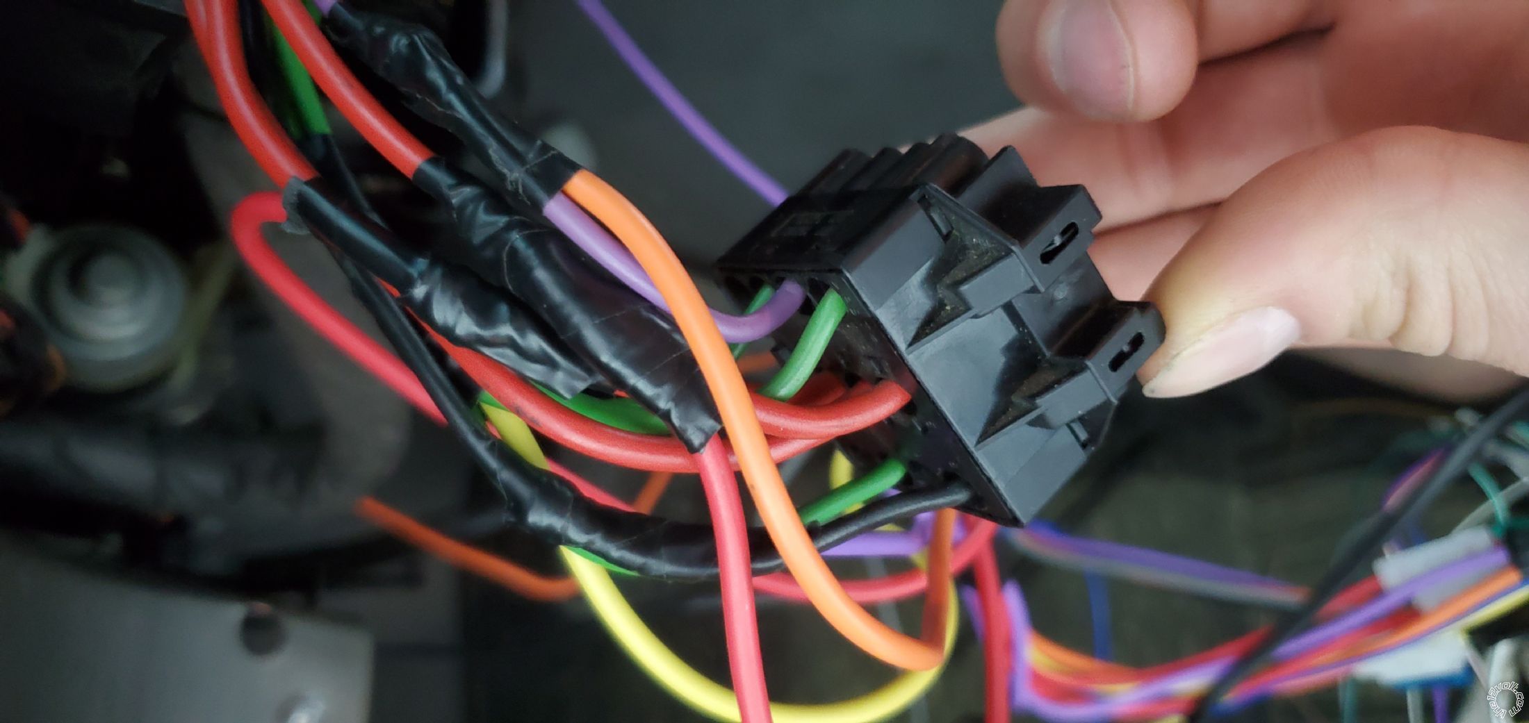
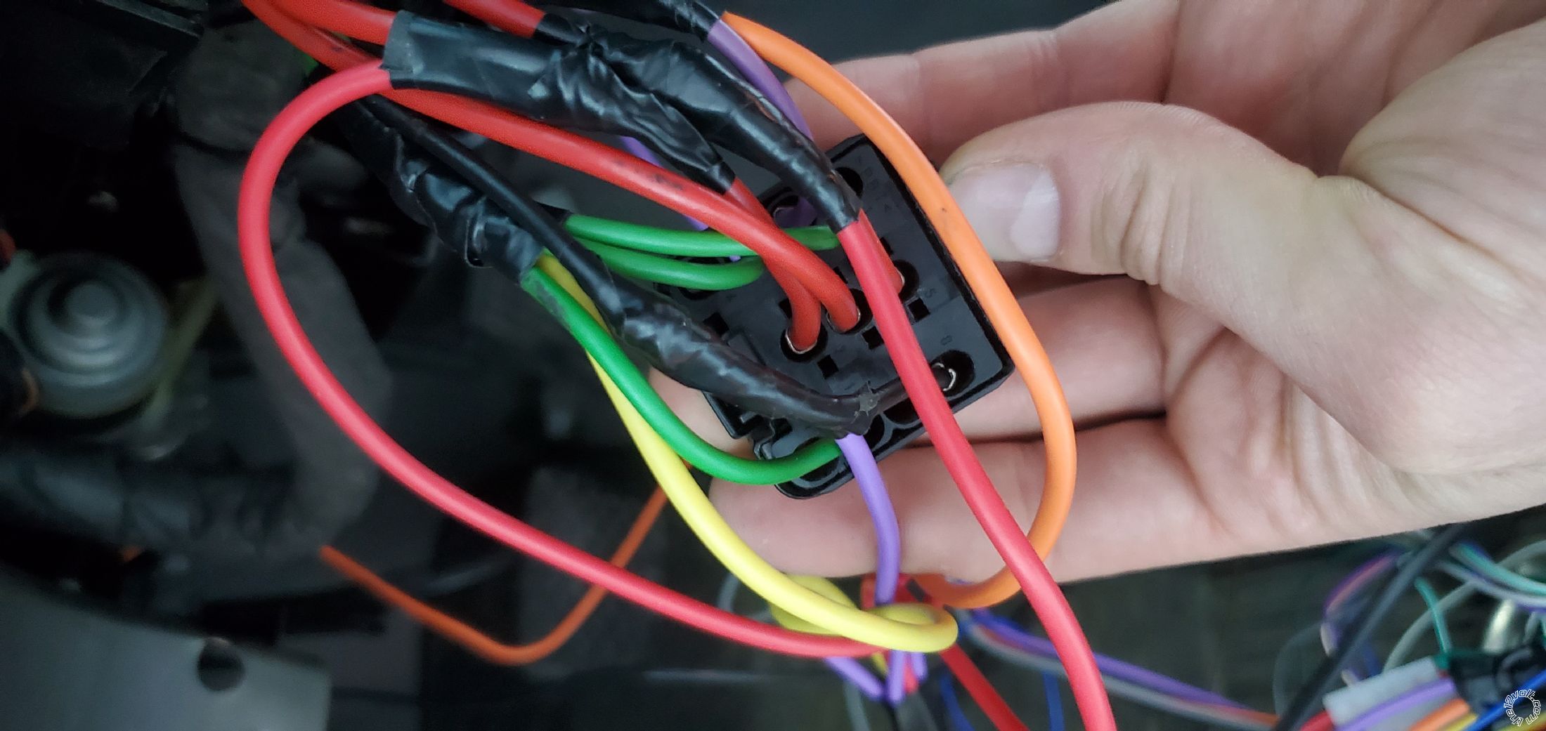
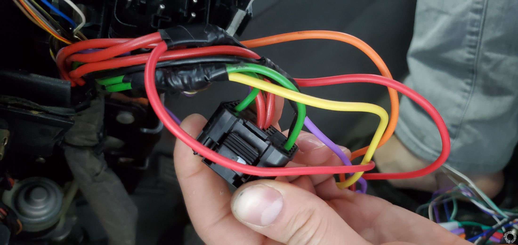
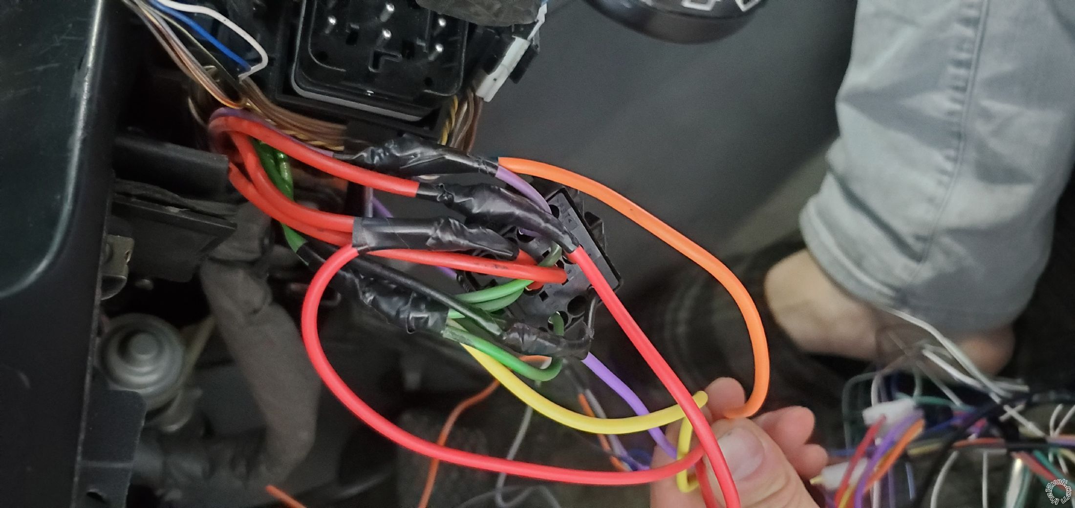
My ignition switch connections:
Pin 1, 3 and 10 are green wires that I understood are all ignition.
I connected the 3 of them together to the yellow (ignition) wire from the module.
Pin 2 is a purple wire I understood to be accessories, so I connected it to the orange wire on the module.
Pins 5, 6 and 7 are all red power wires, 12 volts constant. I spliced wires on pin 5 and 7 and connected them separately to 2 red wires from the starter module. I left red wire on pin 6 intact.
Pin 8 is a black starter wire, so I connected it to the purple starter wire on the module.
Pin 9 is empty
Pin 10 I already covered
Pin 11 is empty
I did my best given some confusing instructions.
For example,
this is showing the starter wire as black/yellow. Mine is plain black.
Another confusion, it shows ignition 1 as green and ignition 2 as purple, but my purple wire is accessories I think.
And I have 3 green wires in total.
The website doesn't list a wire for accessories and shows it N/A, which I figure is incorrect.
The website shows only 1 wire as green for ignition, while I have 3 green wires. And of course the bulldog security website doesn't tell the wires by pin number, so, one is left to guess...
I wish they said, green wire on pin 1 arc.
Now on the
12 volts.com it's also somewhat incorrect. Granted they're talking about e39 530i, while mine is 528i
They only account for 2 green wires while I have 3. At least they label both green wires as ignition, in contradiction to bulldog security website which labeled one green as ignition and 1 purple as ignition.
Both accessories and starter are shown as black/yellow, which is incorrect.
If this was the case, how would one know which black/yellow wire is starter and which is accessories?
I definitely only have 1 black wire. So hopefully it's the purple wire on my ignition switch for accessories and I wired it correctly.
For this reason I was doubting a little bit the way I connected the main wires on the first connector and thought they could cause problems on the other wires on my second connector.


 the12volt
  But with the current state of affairs it's of no use
 Printable version


