the12volt.com spacer
icon

2007 Toyota 4Runner, Compustar CS7502AS, Alarm Only


Post ReplyPost New Topic
< Prev Topic Next Topic >
djdeito 
Copper - Posts: 100
Copper spacespace
Joined: February 19, 2019
Posted: February 25, 2020 at 1:24 AM / IP Logged Link to Post Post Reply Quote djdeito
Below are the connections needed for alarm with keyless entry:
CM600AS module:                         
Connector 1: Main Harness:          Vehicle’s ignition 8 pin connector
Red:               (+) 12 volt          to     12 volt (+) Red. pin#7
Red/White:     (+) 12 volt          to     12 volt (+) White/Blue. pin#2
Green:           (+) 12 volt ignition     to     ignition (+) Black/Red. pin#6
Black:           (-) Ground          to     Chassis Ground
Connector 2:
Green/White:     (-) Parking light output     to     parking light (-) green. pin#8
Gray/Black:        (-) Hood pin input. you may need to install a hood pin
Connector 3:
Brown:     (+) Siren output
Red/White     (+) or (-) Door trigger input (someone else with dome light supervision knowledge could provide some advice as to if a relay is needed to connect the Red/White wire from the alarm module to the vehicle’s dome light wire)
Connector 4: Lock harness:
Blue:           (-) Unlock output     to     Green. White 18 pin plug, pin#8
Blue/Black:      (-) Lock output     to     Blue. White 18 pin plug, pin#6
Connector 6:     Antenna port
Connector 7:     Alarm LED
Connector 8:     Shock Sensor
Notes:
Hood pin input. (Triggers the alarm if the hood is opened while the alarm is armed)
Parking light output (gives you visual confirmation when locking/unlocking. parking lights will flash if alarm is triggered)
Option 1-03: you may want to enable “double pulse unlock” so that all doors open with a single press of the “unlock button”
Option 2-08 siren duration: you may want to change the default value from 30 seconds to 120 seconds
both options can be changed using the remotes as described in the CM600AS installation manual page 19-20. if you do not have this manual let us know.
romzombie 
Copper - Posts: 72
Copper spacespace
Joined: February 05, 2020
Location: Oregon, United States
Posted: February 25, 2020 at 4:21 PM / IP Logged Link to Post Post Reply Quote romzombie
Thank you very much for that. I appreciate it.
Edit - still a little confused. Is it Red from alarm to red 7th pin. Red/white from alarm to white/blue pin 2. Green to black/red and so on....?
djdeito 
Copper - Posts: 100
Copper spacespace
Joined: February 19, 2019
Posted: February 25, 2020 at 5:22 PM / IP Logged Link to Post Post Reply Quote djdeito
No problem. do not get overwhelmed by the amount of connections your vehicle requires to make this work. You will soon gain confidence after making the first couple of wire connections. And after you have successfully hooked up the alarm system, the feeling of accomplishment will be priceless.
one more thing, use a digital multimeter to test the wires in your vehicle before connecting them to your alarm module.
djdeito 
Copper - Posts: 100
Copper spacespace
Joined: February 19, 2019
Posted: February 25, 2020 at 5:43 PM / IP Logged Link to Post Post Reply Quote djdeito
correct, these 4 wire connections go from the compustar alarm module to the vehicle's 8-Pin connector at the ignition switch.
djdeito 
Copper - Posts: 100
Copper spacespace
Joined: February 19, 2019
Posted: February 25, 2020 at 6:48 PM / IP Logged Link to Post Post Reply Quote djdeito
Here you go, i hope this diagrams helps clarify your concern:
2007 Toyota 4Runner, Compustar CS7502AS, Alarm Only - Page 2 -- posted image.
romzombie 
Copper - Posts: 72
Copper spacespace
Joined: February 05, 2020
Location: Oregon, United States
Posted: February 25, 2020 at 9:26 PM / IP Logged Link to Post Post Reply Quote romzombie
I've finished the first plug. Im just wondering about the other wires. The rest dont splice into an existing circuit right? They take the place of the factory wiring right? The siren is hooked up to brown and i grounded the siren in the engine bay. So i need a door trigger to sound alarm and lock/unlock....oh yeah the parking light flash. That wire gets spliced into the connector wire thats attached to the turn signal stalk?
djdeito 
Copper - Posts: 100
Copper spacespace
Joined: February 19, 2019
Posted: February 26, 2020 at 8:56 AM / IP Logged Link to Post Post Reply Quote djdeito
The rest of the wires from Connector 1 of the alarm module do not need splicing to any circuit in your truck. These will be required if you want remote starter. insulate the end of those unused wire in the main harness of the alarm module and bundle them neatly together for future use.
The ground of the siren must be connected to bare metal unpainted surface. The same goes for the ground of the main harness of the alarm module.
Below is the door lock/unlock wires connections. The door lock/unlock are located in the driver’s kick panel
2007 Toyota 4Runner, Compustar CS7502AS, Alarm Only - Page 2 -- posted image.
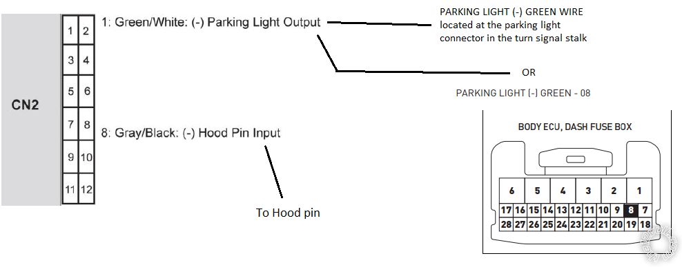
Below is the parking light wire connection. You can find the parking light wire in two different locations in your truck: @ HEADLIGHT SWITCH or BODY ECU, (TOP, WHITE, 26-Pin or 28-pin Plug) Pin 8. NOTE: the BODY ECU is attached to the back of the DASH FUSE BOX, it has 3 plugs on the Right side Edge. Either way, the polarity of the parking light wire in these locations is "negative" and this wire will test "negative" when the parking light switch is in the "ON" position. use your digital multimeter to test this wire before splicing into it as you would do with any other wire.
2007 Toyota 4Runner, Compustar CS7502AS, Alarm Only - Page 2 -- posted image.
djdeito 
Copper - Posts: 100
Copper spacespace
Joined: February 19, 2019
Posted: February 26, 2020 at 12:55 PM / IP Logged Link to Post Post Reply Quote djdeito
See below for the location of the door trigger wire in your truck. Grab your multimeter and set it to "DC voltage" connect the negative probe of the multimeter to your truck's "door trigger purple/yellow wire" and connect the positive probe of the multimeter to constant 12 volt in your truck. close all doors, your multimeter should show 0 volt. Open ONLY the driver door and see if your multimeter shows 12 volt, if it does then close the driver door. Now, open the passenger door ONLY and see if your multimeter shows 12 volt, if it does then close the passenger door and continue to test the remaining doors, they should also show 12 volt ONLY when they are opened. You have found the proper "door trigger wire" in your truck if your multimeter shows 12 volt ONLY when any of the doors are opened.
DOOR TRIGGER PURPLE/YELLOW (-) @ BODY ECU,(TOP, WHITE, 26-Pin Plug) Pin 12, NOTE: the BODY ECU is attached to the back of the DASH FUSE BOX, it has 3 plugs on the Right side Edge.
if the above testing is successful, see below diagram first before splicing the door trigger input wire from the alarm module to your truck. if the above testing is not successful then we will need to splice into the dome light wire:
2007 Toyota 4Runner, Compustar CS7502AS, Alarm Only - Page 2 -- posted image.
romzombie 
Copper - Posts: 72
Copper spacespace
Joined: February 05, 2020
Location: Oregon, United States
Posted: February 26, 2020 at 5:04 PM / IP Logged Link to Post Post Reply Quote romzombie
Thank you so much. Just to be clear, no wires are cut off from factory plugs but alarm wires are spliced into factory wiring at or near the factory plugs?
djdeito 
Copper - Posts: 100
Copper spacespace
Joined: February 19, 2019
Posted: February 26, 2020 at 5:20 PM / IP Logged Link to Post Post Reply Quote djdeito
Correct, no need to cut any wires. No need to splice "at" the factory plugs. Splicing "near" factory plugs is fine.
Page of 13

  Printable version Printable version Post ReplyPost New Topic
You cannot post new topics in this forum
You cannot reply to topics in this forum
You cannot delete your posts in this forum
You cannot edit your posts in this forum
You cannot create polls in this forum
You cannot vote in polls in this forum

  •  
Search the12volt.com
Follow the12volt.com Follow the12volt.com on Facebook
Friday, April 19, 2024 • Copyright © 1999-2024 the12volt.com, All Rights Reserved Privacy Policy & Use of Cookies
Disclaimer: *All information on this site ( the12volt.com ) is provided "as is" without any warranty of any kind, either expressed or implied, including but not limited to fitness for a particular use. Any user assumes the entire risk as to the accuracy and use of this information. Please verify all wire colors and diagrams before applying any information.

Secured by Sectigo
the12volt.com spacer
Support the12volt.com
Top
the12volt.com spacer