the12volt.com spacer
icon

2003 Ford Focus and Avital 5105L


Post ReplyPost New Topic
< Prev Topic Next Topic >
kreg357 
Platinum - Posts: 7,783
Platinum spaceThis member has made a donation to the12volt.com. Click here for more info.spaceThis member has been recognized as an authority in Electrical Theory. Click here for more info.spaceThis member has been recognized as an authority in Mobile Security and Convenience. Click here for more info.spacespace
Joined: January 30, 2009
Location: Pennsylvania, United States
Posted: August 26, 2020 at 2:16 PM / IP Logged Link to Post Post Reply Quote kreg357
Also, on the shock sensor there is a green wire.. I just ignore this wire as its for expandability right?
I'm not a big DEI person but I believe you are correct.
Soldering is fun!
xesvuli420 
Member - Posts: 33
Member spacespace
Joined: August 12, 2020
Posted: August 26, 2020 at 2:52 PM / IP Logged Link to Post Post Reply Quote xesvuli420
Well let’s talk about this, according to my diagram I don’t cut the BLACK/RED, I just connect to it with a diode to the door lock output. Is that incorrect? (I do cut all the trigger wires, but not the lock/unlock wires.. right)
Also on this wire I get constant ground, but it’s the only BLACK/RED one down here. I don’t quite understand it, but if it’s the only one than it has to be the right one correct? Should I just attach It with a diode with the band on the Avital side of the door lock output?
I also need some clarification on all the BLACK/YELLOW wires. I only have 2 in this loom. One has been confirmed to throw ground when the trunk open button is pressed, The other is the same as above, Its constant ground while locked, unlocked, whatever.
I’m also confused because on the schematic, it is mentioned as the unlock all doors wire, but in the same location I’’m supposed to have another BLACK/YELLOW that is supposed to be driver door trigger that I am supposed to cut, and also a lift gate “lamp” BLACK/YELLOW trigger wire also in this same spot.. Am I supposed to be using the BLACK/YELLOW trunk wire that signals when I hit the button or is there a separate “Lamp” wire I also need to find.
I feel like I’m totally missing something here.
Time for more water 🤓
kreg357 
Platinum - Posts: 7,783
Platinum spaceThis member has made a donation to the12volt.com. Click here for more info.spaceThis member has been recognized as an authority in Electrical Theory. Click here for more info.spaceThis member has been recognized as an authority in Mobile Security and Convenience. Click here for more info.spacespace
Joined: January 30, 2009
Location: Pennsylvania, United States
Posted: August 26, 2020 at 4:18 PM / IP Logged Link to Post Post Reply Quote kreg357
Yes, only the door trigger wires need to be cut, not the door lock wire. While it is temporarily invasive, cutting the wire to verify it's function is one way to verify it. With solder and heat shrink tube, the repair is solid and reliable. The cut test and the Avital connection test should not cause any harm and will verify the wire. Of course, for certainty, you could go directly to the GEM, Grey 23 Pin Plug, Pin 15 for the Black/Red Lock wire. The Black/Yellow for Unlock is at the GEM, same plug, Pin 16. The Black/Yellow door trigger wire can be found at the GEM, Tan 23 Pin Plug, Pin 22.
While Bulldog Security, Fortin, DEI and iDatalink show the Lock wire as Black/Red another site has this info
Lock       BLACK/ORANGE       @ DRIVERS KICK PANEL
The 2004 Focus is Black/Orange so this info could be a mistake on this companies part.
I believe that I noticed that multiple Black/Yellow wire issue while researching your project. Pretty sure they come from different pins on the GEM. Hopefully they test via DMM without issue.
The only Focus from that era I kept notes on was a 2003 ZX3 that didn't even have power locks. I added an aftermarket power lock kit with the R/S system so I never had to look for the factory lock wires plus no GEM.
Soldering is fun!
xesvuli420 
Member - Posts: 33
Member spacespace
Joined: August 12, 2020
Posted: August 26, 2020 at 7:17 PM / IP Logged Link to Post Post Reply Quote xesvuli420
Ok I am officially mentally exhausted from today!
It has been a long aggravating day of finding multiple wires by color, only to not be the right ones. I'm so wizzed off at the quality of my resources versus the actual application. I still have 1 wire left to hook up, its the blue trunk instant trigger on pin 10 of the 24 pin Avital harness that I am struggling to find. every resource says find it in a different place. I will attempt this again tomorrow. Everything else is hooked up as it should be, or at least how it is in the schematics I have been following. I wont say I didnt make any mistakes, but I really really tried my best to make solid connections, and tape them tight.
Anyways, so the good news is the fuse didnt pop when I put it in... and thats about it lol.
I put the fuse in, when nothing popped or started smoking I sat in the car, held my breath and hit LOCK on the Avital remote.
To my sheer disbelief all 4 doors locked, I'm not 100% sure, but It definitely made a thunk sound in stereo. I'll check each one soon enough. I hit unlock, all seemed to unlock. I hit lock again and to my disbelief it seemed to function correctly. I decided to test it and make sure my eyes wernt fooling me and grabbed for the inside door handle. I forgot on this car that when you do that It will actually open the door, so of course I set my alarm off for the first time. lmao.
UPDATE
All doors and the trunk do lock and unlock just fine.
Unfortunately I couldnt get it to shut up after that. None of the buttons on either the Avital or Ford fobs stop its siren. I eventually pulled the fuse, and when it shut up I waited about 10 seconds and put the fuse back in and it was still going off. I pulled it out again, laid it down, and decided it was time for a much needed smoke break at this point.
UPDATE
I apparently wasn’t holding down the button long enough. It seems you need to have a longer press to actually activate the buttons.
UPDATE
I already found some problems to track down.
1. After the remote starter starts the car, the starter stays engaged. I wired it how it is on the sheet so I don’t understand how it’s not right, but I’ll pull the column tomorrow.
2. The lights don’t flash for the Avital. I will have to make sure that the polarity isn’t backwards on the module. I think this is supposed to be (-) by default, and I still have the jumper taped to the module from the factory. Now I'm thinking this has to be installed, but installed for the (-) polarity. I had assumed that not using it at all would set it to (-) as I believe it does on older models.
3. The blue light on the valet switch is on when key is off and off when key is on. Cant enter tach learning. Don’t even know where to start, will save this one for last.
4. The trunk release button works, but only if doors are unlocked. If doors are locked, nothing. May be a programming option, haven’t looked it up yet.
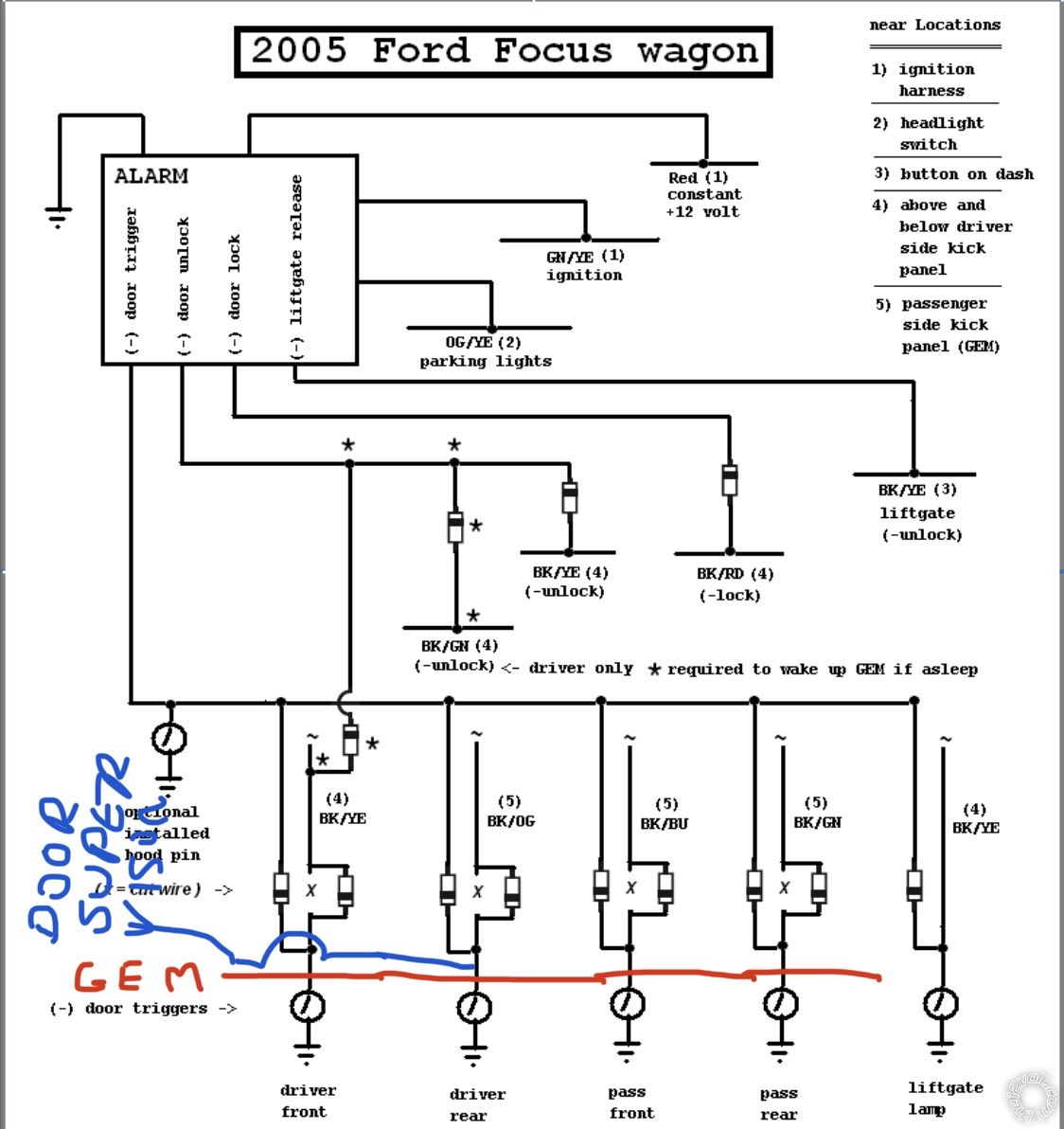
5. I almost wired the GEMS correctly. The Avital will wake the GEM up and unlock all doors on the 2nd push, but unfortunately the driver door doesnt unlock on the first.
UPDATE
I forgot I have to program The double pulse, so this may be normal.
6. The horn doesnt sound while arming or disarming.. I'm not even sure it is "arming" and "disarming". Still seems more like just unlocking and locking only.
I can tell I have another day(s) work ahead of me.
It seems I have the immobilizer decrypted correct at least. It will crank from afar, just have to get. that starter to shutoff.
Still a long way to go.
kreg357 
Platinum - Posts: 7,783
Platinum spaceThis member has made a donation to the12volt.com. Click here for more info.spaceThis member has been recognized as an authority in Electrical Theory. Click here for more info.spaceThis member has been recognized as an authority in Mobile Security and Convenience. Click here for more info.spacespace
Joined: January 30, 2009
Location: Pennsylvania, United States
Posted: August 26, 2020 at 9:42 PM / IP Logged Link to Post Post Reply Quote kreg357
1. Did you program the 5105 Menu 3, Item 1 to Tach ( Option 4 )? Did you do a sucessful Tach Learn?
2. Yes, install Parking Light jumper in the (+) position.
3. Not a big Avital person. System in alarm? System locked?
4. Not sure. How does the factory FOB work? I've seen Toyota's where the sliding doors won't open until car is unlocked. Most systems give option to output unlock along with Trunk Release.
5. Strange but you might need to go with a relay and 5 wire REV wiring on the Driver Door Motor unlock wire. Driver Door Unlock   WHITE/BLACK (+)   AT MODULE IN PASS. KICK
6. Does the horn sound when to press Lock on the Avital remote twice in a row?
Soldering is fun!
xesvuli420 
Member - Posts: 33
Member spacespace
Joined: August 12, 2020
Posted: August 27, 2020 at 11:48 AM / IP Logged Link to Post Post Reply Quote xesvuli420
1. No, I cant seem to get the tach learn to work. In my instructions, the first thing youre supposed to do is to learn the tach. To learn the tach youre supposed to start the car and within 5 seconds hold down the control center button for 3 seconds. After the 3 seconds the led is supposed to come on indicating successful learn. I start the car, and hold down the button for 3 seconds, but I never get the led conformation that it has been learned. I don't know where to begin to figure this issue out yet. Do you think this is why the starter is staying on? Its worth mentioning that I got my tach signal from yet another BLACK/YELLOW wire from the right side of the fuel rail just in case I tapped the wrong one. I also understand that its common for DIY'rs to install the remote harness incorrectly. Below is exactly how it got wired, anything jump out at you?
Pin 2     12V ACC/STARTER RELAY INPUT     RED/BLACK(+)     RED     AVITAL 10 PIN PLUG, PIN 5
Pin 5     12V IGNITION RELAY INPUT (85)     RED(+)     RED(+)     12v 30a CONSTANT
Pin 6     STARTER INPUT (KEY SIDE OF S.KILL)     GREEN     GREY/BLACK     CUT IGNITION WIRE(KEY SIDE)
Pin 7     STARTER OUTPUT (CAR SIDE OF S.KILL)     VIOLET(+)     GREY/BLACK     CUT IGNITION WIRE(CAR SIDE)
Pin 8     ACCESSORY OUTPUT     ORANGE(+)     YELLOW     IGN BARREL, GREY CONNECTOR, PIN 6
Pin 10     IGNITION INPUT/OUTPUT     PINK(+)     GREEN/YELLOW(+)     IGN BARREL, GREY CONNECTOR, PIN 1
3. I dont even know how, but the solid blue led was because it somehow got into valet mode. I did the instructions to turn off valet mode and the led went off. It now seems to operate correctly. Off while disarmed, 2 blinks while armed.
5. I think I just need to program the double pulse option. It seems that when I hit it the first time, although it doesnt unlock the door, it does wake the GEM. If I set it to double pulse, I believe it will work just fine.
6. No. I can't get it to sound at all unless I hold down the panic on the fob.
7. None of the triggers seem to be working. I can set the alarm, the led blinks 2 times a second or so, but when I open any of the doors, nothing happens at all. the LED continues to blink 2 times a second or so. I'm thinking thats a sign the diodes are backwards correct? Please look at the following diagram and tell me if I interpreted it backwards. I assumed the GEM was in the direction where the "switches" are located at the bottom. Meaning all the diode bands are on the GEM side of the wires. I mean this is the only thing it could be right? This would also explain why the 1st button press wakes up the GEM but doesnt unlock the door right? Have I interpreted the schematic wrong, and the GEM is in the direction of ~, not the switch symbol?
2003 Ford Focus and Avital 5105L - Page 5 -- posted image.
kreg357 
Platinum - Posts: 7,783
Platinum spaceThis member has made a donation to the12volt.com. Click here for more info.spaceThis member has been recognized as an authority in Electrical Theory. Click here for more info.spaceThis member has been recognized as an authority in Mobile Security and Convenience. Click here for more info.spacespace
Joined: January 30, 2009
Location: Pennsylvania, United States
Posted: August 27, 2020 at 3:54 PM / IP Logged Link to Post Post Reply Quote kreg357
1. Your wiring looks correct. Of course, you want to use a DMM on each ignition wire to verify it acts like the type of signal it's supposed to be. You could program the 5105 to Engine Checking Off and verify that the Crank Time is at the DefaULT (0.6 SEC ). With a R/S the Purple Starter wire should output a +12V signal for 0.6 seconds and stop. The engine may or may not start up if this time is too short but it won't continue cranking and it will prove something. Did you use a DMM to verify the Tach Signal. DMM to 20V AC, red lead to Tach source and Black lead to chassis ground. You should see a signal of around 1V that will rise slightly with additional RPM's.
3. If you are in Valet Mode the R/S function should work...
5. You could be right. The iDatastart diagrams only show the two Unlock wire connections.
6. Will the horn work via the steering column button? If yes, did the Black/Blue horn wire test as a (-) wire? Did you double check the connection? Did you test the 5105 to see if it is outputting a (-) Horn signal with a two press Lock?
7. Well, you can drop back 20 yards on this one. First lets discuss the diodes. The diodes placed in the run from the trigger wire to the 5105's single wire (-) Door Trigger Input are for isolation. The diodes placed in the cut Door Trigger wire going from the door switch to the GEM are to prevent 5105 false alarms. You can remove all the diodes for now and just concentrate on one Door Trigger wire. Lets work with the Drivers Door Trigger wire. That's all the 5105 needs to see to set and trigger an alarm condition. So with all the diodes removed and the cut wires reconnected, attach the 5105 Green input wire directly to the Black/Yellow Front Drivers door trigger wire (that was tested and verified) between the reconnected cut and the door pin switch. Lock the car with the 5105 and allow the alarm to set. Open the Drivers Door. The 5105 Brown Siren output wire should go to +12V. The Parking Lights should flash. If that works properly, add the diode to the 5105 door trigger input wire, band towards the car/away from the 5105. Try the test again. If all is OK, add the diode to the Black/Yellow vehicle trigger wire at the previous cut with the band towards the door pin switch. Run the test again. If things are still working OK add the next door and test that door...
Soldering is fun!
xesvuli420 
Member - Posts: 33
Member spacespace
Joined: August 12, 2020
Posted: August 29, 2020 at 2:58 PM / IP Logged Link to Post Post Reply Quote xesvuli420
Ok I did the test on the tach wire. with engine running its around 8v, and seems to go DOWN as I rev. Half throttle took me down to 7v. Im guessing even though this wire is BLACK/YELLOW AND at the fuel rail, its not the correct tach wire? Im starting to have nightmares of BLACK/YELLOW snakes! lmao. Im gonna try and find one that increases with engine RPM as you stated.
Consider the parking lights fixed!
Ive also fixed a couple unrelated issues.
Now its time to find out whats up with the horn.
lmao Im trying to do the damn diodes last, not looking forward to that upside down headache.
Hope all is well, see ya soon!
kreg357 
Platinum - Posts: 7,783
Platinum spaceThis member has made a donation to the12volt.com. Click here for more info.spaceThis member has been recognized as an authority in Electrical Theory. Click here for more info.spaceThis member has been recognized as an authority in Mobile Security and Convenience. Click here for more info.spacespace
Joined: January 30, 2009
Location: Pennsylvania, United States
Posted: August 29, 2020 at 3:16 PM / IP Logged Link to Post Post Reply Quote kreg357
Be careful with the Horn wire. Ford has a bad habit of including them with the Air Bag wire harness ( yellow connectors ).
For the Tach, is that 7V AC? You want to set the DMM to AC for the Tach, everything is DC. You could go with Engine Checking = OFF and set a fixed crank time of 0.6 seconds just to test the continuous cranking condition.
Soldering is fun!
xesvuli420 
Member - Posts: 33
Member spacespace
Joined: August 12, 2020
Posted: August 29, 2020 at 3:55 PM / IP Logged Link to Post Post Reply Quote xesvuli420
Yea and guess what color every single one of the 5 clips on the GEM are..? YELLOW! For an hour I looked elsewhere for a GEM because I thought it was some type of airbag module. I will be super careful on this horn circuit!
No I mistakenly had it still in dc. I didnt catch it above. thought me something new today, I had no idea you used AC for anything but the ignition/charging systems. Neat! Lucky for me though, I just decided to hook the BLACK/ORANGE up to the R/S and see what happened. I don't know what in the heck the BLACK/YELLOW wire is, but it sure as doodie isnt for the remote start. As soon as I tied in the BLACK/ORANGE the remote start works PERFECTLY! Thank goodness, one of my bigger issues is now off the table.
Ok talk soon, back to work for the horn.. but I don’t understand how it will work during alarm going off, but won’t during setting... holding down the panic, or activating the shock sensor sets the thing to honking, how would this work if my tie in to the blue wire wasn’t good?
Page of 6

  Printable version Printable version Post ReplyPost New Topic
You cannot post new topics in this forum
You cannot reply to topics in this forum
You cannot delete your posts in this forum
You cannot edit your posts in this forum
You cannot create polls in this forum
You cannot vote in polls in this forum

  •  
Search the12volt.com
Follow the12volt.com Follow the12volt.com on Facebook
Thursday, April 25, 2024 • Copyright © 1999-2024 the12volt.com, All Rights Reserved Privacy Policy & Use of Cookies
Disclaimer: *All information on this site ( the12volt.com ) is provided "as is" without any warranty of any kind, either expressed or implied, including but not limited to fitness for a particular use. Any user assumes the entire risk as to the accuracy and use of this information. Please verify all wire colors and diagrams before applying any information.

Secured by Sectigo
the12volt.com spacer
Support the12volt.com
Top
the12volt.com spacer