the12volt.com spacer
icon

2003 Ford Focus and Avital 5105L


Post ReplyPost New Topic
< Prev Topic Next Topic >
kreg357 
Platinum - Posts: 7,783
Platinum spaceThis member has made a donation to the12volt.com. Click here for more info.spaceThis member has been recognized as an authority in Electrical Theory. Click here for more info.spaceThis member has been recognized as an authority in Mobile Security and Convenience. Click here for more info.spacespace
Joined: January 30, 2009
Location: Pennsylvania, United States
Posted: August 22, 2020 at 2:35 PM / IP Logged Link to Post Post Reply Quote kreg357
Yes it is a programming option with the Avital 5105.
Soldering is fun!
xesvuli420 
Member - Posts: 33
Member spacespace
Joined: August 12, 2020
Posted: August 23, 2020 at 5:01 PM / IP Logged Link to Post Post Reply Quote xesvuli420
ok, I'm building the harness now and wanted to clarify a few things before I tape it up.
1. Is it ok to connect the black wire for parking brake ground on the the Avital 5 pin, pin 1 to the Avital 24 pin, pin 13, black chassis ground wire?
2. Is it ok to connect both the red and the red/black wire for constant 12v on the Avital 10 pin plug, pins 2 and 5, to the Avital 5 pin plug, pin 3, red 12v wire?
3. Is it ok to connect the yellow wire for ignition on the Fortin 20 pin plug, pin 1, to the Avital 10 pin plug, pin 6, green Ignition(key side) wire?
Thanks again for these answers, just want to make sure the harness is a efficient as it can be.
kreg357 
Platinum - Posts: 7,783
Platinum spaceThis member has made a donation to the12volt.com. Click here for more info.spaceThis member has been recognized as an authority in Electrical Theory. Click here for more info.spaceThis member has been recognized as an authority in Mobile Security and Convenience. Click here for more info.spacespace
Joined: January 30, 2009
Location: Pennsylvania, United States
Posted: August 23, 2020 at 5:25 PM / IP Logged Link to Post Post Reply Quote kreg357
Answers:
1. Yes. I do that and run the thicker wire to vehicle ground.
2. Maybe. The two thicker 10 Pin plug wires can be combined and run to the 30 amp supply at the ignition switch harness. The only slight issue is while the 5105 doesn't draw much power internally, you are running a (+) Parking Light output. Chances are you could combine all Reds and run off that lone 30 amp vehicle supply but...   I would look for another +12V constant source and connect the 5 pin Red to that.
3. Probably a typo. You can connect the EVO-ALL Yellow IGN input wire to the Avital thick Pink IGN1 wire right by the 5105 and then run that same Pink wire to the vehicles IGN wire at the ignition switch harness.
Soldering is fun!
xesvuli420 
Member - Posts: 33
Member spacespace
Joined: August 12, 2020
Posted: August 23, 2020 at 6:01 PM / IP Logged Link to Post Post Reply Quote xesvuli420
Awesome, Thank you! I have connected the red/black to the red on the 10 pin harness. Then I'll connect the red on the 10 pin harness to the 30 amp supply at the ignition switch. Ill then connect the red from the 5 pin to somewhere in the fusebox with constant 12v. I'm getting so close I can taste it. Sundays are my day to do absolutely nothing, but as you see ive been bitten by the bug.
I also wanted to share with you my ugly monster! Normally I'm the type to twist the wires with the drill, but I am way too new for that magic trick. Its a pack of zipties and black tape for the first one, and I'm already glad I made that decision as ive had to re do the routing like 3 times to get it where I'm happy. I sure hope I got it all right, that black tape seems to melts into itself.
Anyways here it is in all its glory, please dont mind the dirty porch its well used and as you can see needs a dusting!
2003 Ford Focus and Avital 5105L - Page 4 -- posted image.
kreg357 
Platinum - Posts: 7,783
Platinum spaceThis member has made a donation to the12volt.com. Click here for more info.spaceThis member has been recognized as an authority in Electrical Theory. Click here for more info.spaceThis member has been recognized as an authority in Mobile Security and Convenience. Click here for more info.spacespace
Joined: January 30, 2009
Location: Pennsylvania, United States
Posted: August 23, 2020 at 6:17 PM / IP Logged Link to Post Post Reply Quote kreg357
Looks good. On the next one, get yourself a roll of Tesa Tape #51036. The 3/4" width is a good size. Makes the harness runs look factory and it leaves no residue if you have to make changes.
Soldering is fun!
xesvuli420 
Member - Posts: 33
Member spacespace
Joined: August 12, 2020
Posted: August 23, 2020 at 6:27 PM / IP Logged Link to Post Post Reply Quote xesvuli420
Great tip! Sounds like something i need to add to my next amazon order.
I made a quick install version of my sheet. Its looking more and more manageable every day! I still have to get a relay and make some diode wires, but this install is about to hit high gear.
PDF
EXCEL
Thank you again bro for being on this forum, and participating in my thread. Im already at max capacity for appreciation for you sir!
xesvuli420 
Member - Posts: 33
Member spacespace
Joined: August 12, 2020
Posted: August 25, 2020 at 7:16 PM / IP Logged Link to Post Post Reply Quote xesvuli420
Hello again!
I'm 5 wires away from completing all the necessary connections and powering up the Avital module for the first time. I saved the sonofabeeche connections for last. Im down to the driver kick panel for the unlock, lock, dome light supervision, and the instant door/trunk triggers. Of course that requires doing the GEM wakeup as part of the installation. I will tackle this tomorrow, but its got me thinking, now that all the tedious work is over, I have no idea about what to expect when I finally plug that 12v constant from the 5 pin plug into the fuse panel for the first time.
I also assume at this point since my starter wire has been cut and spliced into the Avital that the car is dead now until I finish the install and plug in the Avital's 12v power wire to let it take its control.. Is this correct or will the car still start with the power off to the Avital module? I'm just curious about that. I dont plan on touching the key until after tomorrow.
Speaking of tomorrow, please let me know what to expect when I finally take the system online. I will wire up the GEM wakeup first, and save the 12v to the Avital to be the very last wire connected. When I plug that 12v connection in, and the Avital gets a closed circuit for the first time, assuming I have done a good job on all the connections, what do I need to expect? What do I do next? I have the Avital to program, at least to a double pulse unlock, and also the Fortin module needs to be programmed. I have a doodie ton to read tonight on the Decrypter instructions, as well as the Avitals operations, but a laymans approach would be appreciated!
Tomorrow is either going to be a great day, or a horocious one depending on my install to this point. Please keep this Noob in your thoughts as the moment of truth comes to present!
kreg357 
Platinum - Posts: 7,783
Platinum spaceThis member has made a donation to the12volt.com. Click here for more info.spaceThis member has been recognized as an authority in Electrical Theory. Click here for more info.spaceThis member has been recognized as an authority in Mobile Security and Convenience. Click here for more info.spacespace
Joined: January 30, 2009
Location: Pennsylvania, United States
Posted: August 25, 2020 at 9:47 PM / IP Logged Link to Post Post Reply Quote kreg357
What happens when I plug in the R/S system?
The fuses should be removed and all the R/S harnesses plugged in. When all is ready, plug in the fuses. What happens depends on the vehicle / system / bypass module, etc. In your case, not too much. Verify that the fuse(s) doesn't blow. Next ensure that the car works like normal with the factory remote and starts with the key.
The cut Starter wire will not be an issue if you made proper connections to it. The internal Starter Kill relay has the cut Starter wire going thru it, Pin 87a to Pin 30, so even without R/S power the car will start like normal.
Your next step is to program the EVO-ALL bypass module to the car. If you only have one working key, follow the 1 Key programming procedure. Verify that each step follows the guide. You might have to scroll down to see all DCryptor info on the PC screen and complete that process.
After that you can warm up the engine and do the Tach Learn process as detailed in the Avital install manual.
Next would be to test the Avitals Lock and Unlock control. Test the Unlock before the 2 minute GEM sleep and then test after the 2 minute sleep. Try a trunk release.
Verify that the Parking Lights flash with lock and unlock.
Try a R/S. Watch the Instrument Panel to see the ignition come ON and then the engine cranks. Look for any "Security" indicators on the IP. If the engine starts, listen for over/under crank. Let it idle for a minute and then depress the Brake Pedal. The engine should shutdown. Start the engine again and then pop the hood. The engine should shutdown. Start the engine again and try a "key takeover" by inserting the key, turning to RUN and then stepping on the Brake Pedal. The Parking Lights should go off and the engine should keep running.
The Avital RKE functions can work even though the R/S function has problems and visa-versa. If there are any issues, look at them one at a time. Typically, if your planning, prep and connections are correct and solid, you won't have any issues. Setting the Avital to Double Pulse Unlock can be the last thing you do, and it might be the most difficult ( using the Avital remotes ). Take your time, drink plenty of water and enjoy the moment.
At this point you can test the Avital's alarm system.
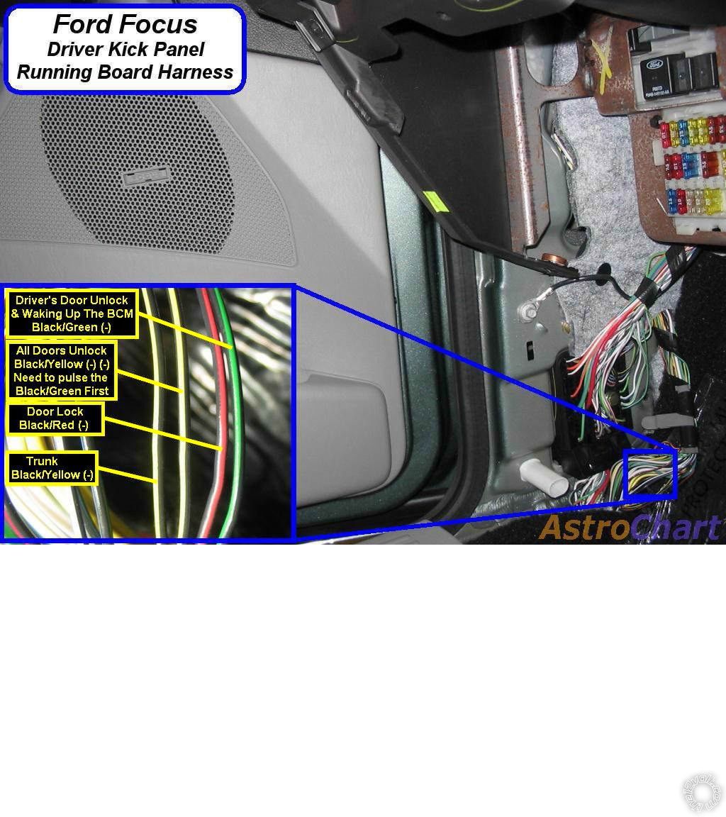
Below is some info on the lock wires.
2003 Ford Focus and Avital 5105L - Page 4 -- posted image.
Soldering is fun!
xesvuli420 
Member - Posts: 33
Member spacespace
Joined: August 12, 2020
Posted: August 26, 2020 at 12:48 PM / IP Logged Link to Post Post Reply Quote xesvuli420
Well that didnt take long lol. Im stuck already. I decided to start on my easiest wire and try to tackle the LOCK trigger. I looked at my schematic and went off in search of a BLACK/RED. I found one above the kick panel and wired in the diode... Then I got to thinking I had better not assume anything so I went back to the loom and sure enough was another BLACK/RED. I disconnected the diode and hooked the meter up to verify its locking function. To my surprise its fully grounded with key off. I hooked my meter up red side to a 12v constant at the fuse panel, and then black side to the BLACK/RED. It imediately gives me 12v on the display.
If I understand this correctly I should get a pulse of ground when the LOCK function is activated by the doors or remote.
So I moved on to the other BLACK/RED wire. It also is fully grounded.
So I decided to come back here for an explanation or what i'm doing wrong, and I saw your post with the included picture showing wire location. Your BLACK/RED is located a totally different location. A much better accessible location then I was way up inside the back of the dash behind the fuses. I just figured the guy that drew out the GEM bypass module didn't know it was here too.
So I pull up the carpet and whatever you call the sound blanket underneath and I locate the BLACK/RED in the pictured loom. It too has ground all the time!
What am I not understanding?!? Should't it be pretty much OFL or close to it until you engage the LOCK feature? So far all the other wires have tested this way. 00.00.01 or something like that, and then 11.##+ when I activate funtion.
I'm gonna need more water lol.
I installed an empty 20a fuse for the 12v constant from the 5 pin Avital plug going to the fuse panel. Now when I plug the fuse in the system will hopefully go online.
Also, on the shock sensor there is a green wire.. I just ignore this wire as its for expandability right?
Thanks again sir
kreg357 
Platinum - Posts: 7,783
Platinum spaceThis member has made a donation to the12volt.com. Click here for more info.spaceThis member has been recognized as an authority in Electrical Theory. Click here for more info.spaceThis member has been recognized as an authority in Mobile Security and Convenience. Click here for more info.spacespace
Joined: January 30, 2009
Location: Pennsylvania, United States
Posted: August 26, 2020 at 2:06 PM / IP Logged Link to Post Post Reply Quote kreg357
Your basic understanding on the (-) signals is correct. Ignoring what you see when you're in a static condition, you should see the +12V when you have the signal present. Sometimes to see a lock signal the wire used is actually the lock cylinder key output. This means to see the wire under test do anything you must insert the key into that doors' lock cylinder and rotate the key. I typically use a "computer safe" LED test light. It will show a Green LED when a (-) signal is present and a Red LED with a (+) signal is present. Being as you are cutting this wire to add the diode, you could cut the wire and test the lock function ( with key, button and/or FOB ) to see if it is the right wire.
I have had a few where there is no way to test the wire. In those rare situations I do everything to ensure I'm on the correct wire from all of the available wiring sources and very sure it's the correct wire, then I connect the R/S's lock wire and press Lock to see if it works the circuit. This is a better way than using a jumper to chassis ground because the R/S's lock output is rated at 200mA. In your case I'm sure there are several Black/Red's in the door sill bundle. Go by gauge, appearance, proximity to unlocks wires and testing to rule out other wires, etc. Worst case, go to another location where the Plug and Pin are specified.
I had one where the customer lost the factory remotes so I couldn't use them to test for the trunk pop wire. The interior release was mechanical, so no help there. The wire guides said it was a (+) signal in a Brown wire in the door sill harness. There were 4 Brown wires in that harness... I ended up going into the trunk. removing trim to see the trunk solenoid connector to get an idea of Brown wire color and gauge, then found the most likely wire in the door sill. Cut it and them
ohmed it out to the trunk solenoid connector. Simple job took an extra 30 minutes.
Soldering is fun!
Page of 6

  Printable version Printable version Post ReplyPost New Topic
You cannot post new topics in this forum
You cannot reply to topics in this forum
You cannot delete your posts in this forum
You cannot edit your posts in this forum
You cannot create polls in this forum
You cannot vote in polls in this forum

  •  
Search the12volt.com
Follow the12volt.com Follow the12volt.com on Facebook
Friday, April 19, 2024 • Copyright © 1999-2024 the12volt.com, All Rights Reserved Privacy Policy & Use of Cookies
Disclaimer: *All information on this site ( the12volt.com ) is provided "as is" without any warranty of any kind, either expressed or implied, including but not limited to fitness for a particular use. Any user assumes the entire risk as to the accuracy and use of this information. Please verify all wire colors and diagrams before applying any information.

Secured by Sectigo
the12volt.com spacer
Support the12volt.com
Top
the12volt.com spacer