the12volt.com spacer
icon

2012 Hyundai Accent, Prestige APS-687TWE


Post ReplyPost New Topic
< Prev Topic Next Topic >
mickb24 
Member - Posts: 19
Member spacespace
Joined: January 06, 2021
Location: Oklahoma, United States
Posted: January 12, 2021 at 9:22 AM / IP Logged Link to Post Post Reply Quote mickb24
Hi guys, hope someone can give me some guidance on installing this remote starter on a 2012 Hyundai Accent - Standard key no transponder / immobilizer, this is going into my daughters car.
The car currently has an Anti Grind built in, confirmed by starting car and going past crank with igmition key when car is running, so question is, if started by remote starter will this feature still be on? if not i understand I will need to add a relay, after reading throug the forums here on 12volt I understand that I will need to add it in the following way:
86 to ignition 12v+
85 from Remote Start GWA
87a from ignition switch (Cut Starter wire)
30 to starter side of cut starter wire.
Diode 1N4004 with band towards 86 (ignition 12v+)
This leads me into my next question, I dont see a GWA wire on the APS-687TWE, the best wire I can see is from the 20 pin harness Lt. Blue- (Ground Out While Running) From manual - This wire provides a 300mA ground output that becomes active 1.5 seconds before the Remote Start Unit initializes and remains grounded while running plus an additional 2 seconds after the Remote Start Unit turns off. In all of the applications described below, a relay will be required. Would this be the correct wire?
My second question is regarding the 4 Pin Main Harness. (This is confusing the crap out of me)
I know again after reading the Forum posts that the Parking Lights are (-) Negative.
1. Black Chassis Ground (Got that)
2. White with Red Trace - This wire is the common contact of the on board parking light flasher relay. If the vehicle you are working on has +12 volt switched parking lights, connect this wire to a fused + 12 volt source. (Max. 15 Amps)
NOTE: If the vehicle's parking lights are ground switched, connect this wire to chassis ground.
As stated previously the Parking Light wire on the Hyundai Accent is (-) So I should connect this wire to Ground?
3. Yellow with Black Trace - (+) to Alarm Ignition Input (Dont think I need to use this wire).
4. White wire - Parking Light Relay Output. This wire would connect to the the Pink/Black Parking light wire.
This wire is the normally open contact of the on board parking light flash relay. Connect this wire to the vehicle's parking light feed wire. This is the wire that gets switched on, either (+) or (-), when the vehicle's parking light switch is activated.
kreg357 
Platinum - Posts: 7,783
Platinum spaceThis member has made a donation to the12volt.com. Click here for more info.spaceThis member has been recognized as an authority in Electrical Theory. Click here for more info.spaceThis member has been recognized as an authority in Mobile Security and Convenience. Click here for more info.spacespace
Joined: January 30, 2009
Location: Pennsylvania, United States
Posted: January 12, 2021 at 9:49 AM / IP Logged Link to Post Post Reply Quote kreg357
The cars Anti-Grind will still function during R/S. The starter won't grind if you go past ON during key-takeover.
The Prestige R/S unit has an internal Parking Light relay. The White/Red wire is the input to this relay. It gives the installer the flexibility to select the (-) or (+) signal instead of using a jumper. You are correct, for your Elantra, connect the White/Red to the Black and run the Black to a good Chassis Ground.
GWA is very different from GWR. GWR is typically used to control a bypass module. GWA is typically used for window roll up, etc. What do you need GWA for?
BTW, if you haven't seen it, there is a Pictorial on that vehicle :    https://www.the12volt.com/installbay/forum_posts.asp?tid=139756
Soldering is fun!
mickb24 
Member - Posts: 19
Member spacespace
Joined: January 06, 2021
Location: Oklahoma, United States
Posted: January 12, 2021 at 12:30 PM / IP Logged Link to Post Post Reply Quote mickb24
kreg357. Thank you for the super quick response, so no relay for AntiGrind required, thats good news.
The GWA wire I was wanting to use for the AntiGrind relay, as per howie ll posted as per https://www.the12volt.com/installbay/forum_posts.asp?tid=126899 forum post, but seeing as I dont need it I should be OK.
The pictorial guide you posted is for an Hyundai Elantra, my daughters car is an Hyundai Accent, although there is another pictorial guide for this car at https://www.the12volt.com/installbay/forum_posts.asp?tid=132310 which I have read thouroughly and in this post near the bottom when talking about the Tach wire it states "This is a picture of a Tach source at the #4 Spark Plug Coil. Additionally, the Accent does not have "one-touch-starting" and is a candidate for Starter Kill and/or Anti-Grind. Just read who the author was and I see that you wrote this guide a long time ago - October 04, 2012.
Once again Kreg357 Thank you for the reply, I really do appreciate your help.
howie ll - Posted
Why people are getting flat batteries.
I've seen this posted twice recently and people don't appear to be following the alarm manufacturer's instructions.
An external anti-grind/starter relay should be wired as follows:-
85 Only use the "ground when armed (GWA)" from the alarm.
86 Ignition 1 only.
87a Key side of starter
30 Starter side of cut wire and starter output from R/S.
Diode 1N4004 across 85 and 86 with the band towards 86.
If you join a constant 12V+ to 86 that relay will be on all the time and you will have a flat battery within a day.
kreg357 
Platinum - Posts: 7,783
Platinum spaceThis member has made a donation to the12volt.com. Click here for more info.spaceThis member has been recognized as an authority in Electrical Theory. Click here for more info.spaceThis member has been recognized as an authority in Mobile Security and Convenience. Click here for more info.spacespace
Joined: January 30, 2009
Location: Pennsylvania, United States
Posted: January 12, 2021 at 1:26 PM / IP Logged Link to Post Post Reply Quote kreg357
You're right, got the Elantra Pictorial mixed up with the Accent.
Test to verify you don't need Anti-Grind. You could add it if necessary using the GWR output.
Adding StarterKill would be difficult with the Prestige system.
Soldering is fun!
mickb24 
Member - Posts: 19
Member spacespace
Joined: January 06, 2021
Location: Oklahoma, United States
Posted: January 12, 2021 at 3:15 PM / IP Logged Link to Post Post Reply Quote mickb24
Thank you once again, if I do need AntiGrind, is that still the same wiring on the required relay? Stater wire cut, diode etc.
85 (GWR)" from the Remote Starter.
86 Ignition 1 only.
87a Key side of starter
30 Starter side of cut wire and starter output from R/S.
Diode 1N4004 across 85 and 86 with the band towards 86.
kreg357 
Platinum - Posts: 7,783
Platinum spaceThis member has made a donation to the12volt.com. Click here for more info.spaceThis member has been recognized as an authority in Electrical Theory. Click here for more info.spaceThis member has been recognized as an authority in Mobile Security and Convenience. Click here for more info.spacespace
Joined: January 30, 2009
Location: Pennsylvania, United States
Posted: January 12, 2021 at 4:19 PM / IP Logged Link to Post Post Reply Quote kreg357
Yes, that will work for Anti-Grind if you need it.
Soldering is fun!
mickb24 
Member - Posts: 19
Member spacespace
Joined: January 06, 2021
Location: Oklahoma, United States
Posted: January 15, 2021 at 3:37 PM / IP Logged Link to Post Post Reply Quote mickb24
Just wanted to say thank you for the help, I got it installed today with no issues, you were correct I did not need to add any relays for Anti-Grind.
Took my time and made it look good and double checked everything, took about 3 hours, and if I do say so myself I'm pretty proud of how professional the install looks.
I started with T Taps then tore those things out and soldered everything.
mickb24 
Member - Posts: 19
Member spacespace
Joined: January 06, 2021
Location: Oklahoma, United States
Posted: January 18, 2021 at 8:14 PM / IP Logged Link to Post Post Reply Quote mickb24
Hi guys.
I recently installed a Prestige APS-687TWE in my daughters 2012 Hyundai Accent, no Alarm or Bypass (No Key Transponder) evrything went great, or so I thought.
I have recently discovered 2 issues:
1: The Doors unlock automatically and stay unlocked on remote start. (NOTE 1 Below)
2: The Parking Lights stay on after remote start shuts down, I cannot find any information on how to resolve this, I dont want her to get stranded somewhere with a flat battery.
I have read through the installation manual and also searched this forum, but cant seem to find ny of the same issues I am having.
NOTE 1
The manual has this information on these 2 wires, reads like I need to install one or both of them? But where to? The wiring from Bulldog Security states: GRAY/ORANGE (-) Requires Double Pulse, (drivers door key cylinder) WHITE 39-PIN PLUG, PIN 20 in DRIVERS KICK
14 Black w/ Light Green trace Wire:
Pulsed Ground Output After Start. The Black w/ Light Green Trace wire will provide a 1 second 300mA pulsed ground output after the vehicle is started under control of the remote start unit.
Typically this wire will be used to re-lock the vehicle doors if the doors unlock automatically when the factory anti-theft system is disarmed.
This wire will also activate when the transmitter is used to arm/lock the system.
This output can be selected to operate in a number of different configurations as shown in selectable feature # 21 of Bank 3.
21st: Alt O/P After Start. Pulse After Start. Gnd When Running. O/P Same as Ign 1. O/P Same As Accy. O/P During Crank
16 Black w/ Red trace Wire:
Pulsed Ground Output After Shutdown. The Black w/ Red Trace wire will provide a 1 second 300 mA pulsed ground output 2 seconds after the remote starts GWR wire shuts down.
This output will occur regardless of whether the circuit times out or is manually terminated.
Typically this output will be used to re-lock the vehicle doors if the doors unlock automatically when the ignition circuit transitions to off.
This output is selectable and can function as described in feature selection of bank 3 feature #22.
22nd: Alt O/P Aft Shut Dwn. Pulse Aft Sht Dwn. Gnd When Running. O/P Same as Ign 1. O/P Same As Accy. O/P During Crank
Any help you guys could give I would be eternally grateful.
Thank you.
mickb24 
Member - Posts: 19
Member spacespace
Joined: January 06, 2021
Location: Oklahoma, United States
Posted: January 18, 2021 at 8:37 PM / IP Logged Link to Post Post Reply Quote mickb24
Just reading through the forum again, I found the information psoted by lectricguy.
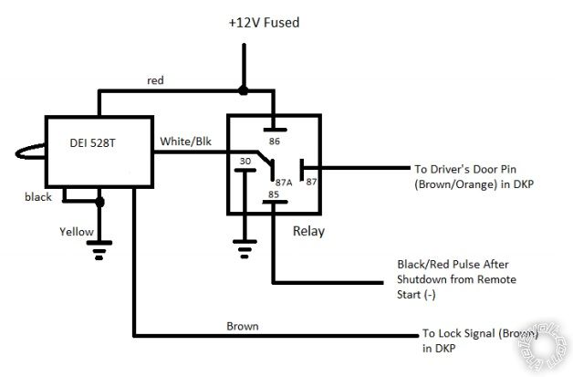
Looks like this should fix both issues I am having, but I just have one question, can I tie the wires from the Timer, Brown and from the Relay Brown/Orange at the same connection points I already made from the remote start Lock and driver door pin, no doides or anything required?
2012 Hyundai Accent, Prestige APS-687TWE -- posted image.
Thank you.
iskidoo 
Silver - Posts: 1,040
Silver spaceThis member has made a donation to the12volt.com. Click here for more info.spacespace
Joined: December 08, 2002
Location: Maine, United States
Posted: January 20, 2021 at 12:07 AM / IP Logged Link to Post Post Reply Quote iskidoo
Looks like you've got the proper wire outputs figured out.
Use 16 Black w/ Red trace Wire: to DOOR TRIGGER     BROWN/ORANGE (-) WHITE 39-PIN PLUG, PIN 39 @ DRIVERS KICK PANEL
This will simulate the door opening after shutdown which should turn the headlights off.
Use 14 Black w/ Light Green trace Wire: to POWER LOCK     BROWN (-) WHITE 39-PIN PLUG, PIN 15 @ DRIVERS KICK PANEL
This should pulse the locks closed after the remote start gets going.
You don't need that timer/relay circuit for anything.
Steve
Steve G
Page of 2

  Printable version Printable version Post ReplyPost New Topic
You cannot post new topics in this forum
You cannot reply to topics in this forum
You cannot delete your posts in this forum
You cannot edit your posts in this forum
You cannot create polls in this forum
You cannot vote in polls in this forum

  •  
Search the12volt.com
Follow the12volt.com Follow the12volt.com on Facebook
Saturday, April 20, 2024 • Copyright © 1999-2024 the12volt.com, All Rights Reserved Privacy Policy & Use of Cookies
Disclaimer: *All information on this site ( the12volt.com ) is provided "as is" without any warranty of any kind, either expressed or implied, including but not limited to fitness for a particular use. Any user assumes the entire risk as to the accuracy and use of this information. Please verify all wire colors and diagrams before applying any information.

Secured by Sectigo
the12volt.com spacer
Support the12volt.com
Top
the12volt.com spacer