"1. Will I need to use any other wires than what is listed here?"
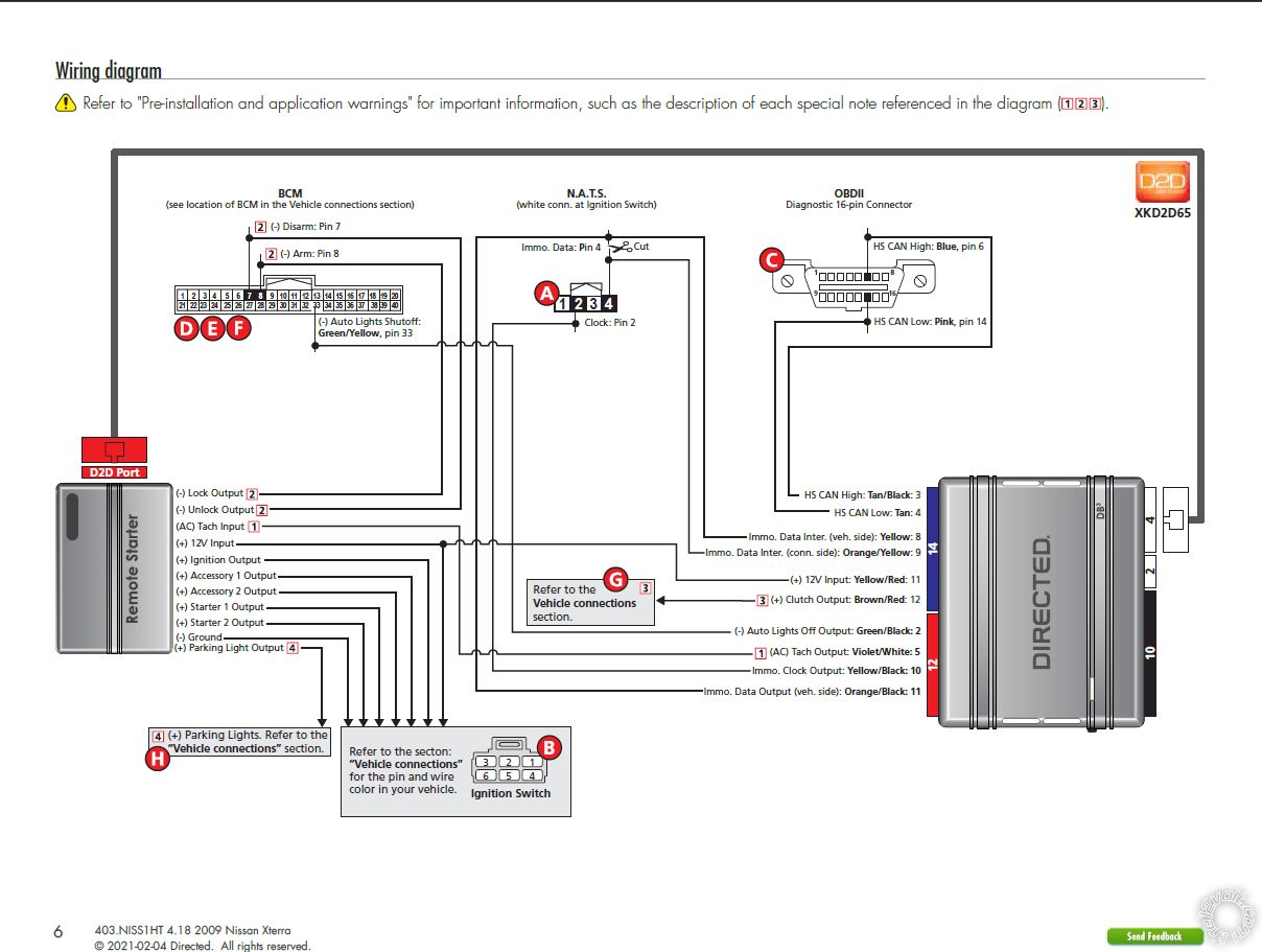
It depends... Does the vehicle have the factory alarm system? Was the DB3 flashed with the 403.NISS1HT v4.20 firmware for your vehicle? The DB3 w/403.NISS1HT Install Guide has a more complete list of required connections. Hopefully the supplier of the DB3 flashed it correctly and supplied you with the 21 page Install Guide. The install guide does have diagrams of the vehicle connectors, etc. If yes, then the DB3 will supply the Tach, Brake, E-Brake, Hood. Trunk and Door pin signals. It will also handle the Transponder bypass, Locks, Parking Lights and Hatch release.
"2. Will the DB3 module allow the car to remote start even without the key present?"
Yes, after the DB3 is successfully programmed to the vehicle it will bypass the vehicles transponder immobilizer system during remote start-up without any key in the vehicle.
"3. My research says that my transmission has a neutral safety wire coming off it which is what the computer uses to tell the transfer case that the transmission is in neutral for 4WD. Can I use this wire to install the remote start like you would in an automatic transmission so that I don't have to go through the manual transmission "shut down" procedure each time?"
Possibly. This is a major safety issue. You must locate this wire and verify that it does indeed indicate that the manual transmission is in neutral and that it only outputs this signal when the transmission is in neutral and at no other times. If this "neutral signal" is a (-) type output, then you could connect it to the Vipers BLACK/WHITE (-) NEUTRAL SAFETY /PARKING BRAKE INPUT wire.
What you are missing...
Clutch bypass - the DB3 has an output for this and the vehicle wire is indicated in the the DB3 install guide.
Accessory 2 power - the Viper 4806 can only supply 4 ignition type outputs ( ING1, Starter1, Starter2 and ACC1. If the ACC2 is required you will need a relay. The DB3 install diagram shows it connected.
Two 1N4001 diodes for the Arm and Disarm wiring.
An in-line fuse holder w/fuse for the ACC2 external relay.
As far as a step by step guide, well...
1. Obtain any extra items ( diodes and relay ) plus Tesa tape, Scotch Super 33+ Electric tape, etc.
2. Make up a wire connection list for all necessary connections. If you post it, the 12V Forum members can review it and make recommendations.
3. Bench Prep the system / modules. Cut unused wires to 3 inches and bundle/insulate. Bundle wires with Tesa Tape in groups by intended end location.
4. Disassemble vehicle and locate/test all needed wires.
5. Remove Viper fuses*, position Viper, run wires and cut to length. Solder all connections. Insulate all connections with electric tape.
6. Run antenna harness to windshield and install antenna.
7. Install fuses.
8. Program DB3 to vehicle successfully.
9. Make any necessary changes to the Viper Programming Option Tables.
10. Do a Viper Tach Learn.
11. Test the Vipers lock and unlock control. Test the Hatch Release.
12. Test the Viper R/S function.
13. Test the Brake shutdown.
14. Test the Hood Pin shutdown.
* I install while hot. I do not unplug vehicle connectors other than N.A.T.S. and main ignition switch connector, if needed.
Soldering is fun!


 This is a major safety issue.
I'm definitely aware of the safety concern with a manual transmission and I'll make sure that if I can't 100% verify that it will be in neutral then I will install it the normal way and use the reservation mode for manual transmissions. I'd just like to be able to do it the other way if possible and read about that neutral wire and got excited.
Clutch bypass
I see that in the diagram. "Clutch Output"?
Accessory 2 power
Looking at that diagram, it looks like more than 4 IGN outputs are needed. Ignition Output, Acc 1 Output, Acc 2 Output, Start 1 Output, and Start 2 Output. I believe I saw a post on these forums or possibly on Youtube about how to set up the relay that's needed. But if you have notes for me that would also be helpful.
Two 1N4001
As in
This is a major safety issue.
I'm definitely aware of the safety concern with a manual transmission and I'll make sure that if I can't 100% verify that it will be in neutral then I will install it the normal way and use the reservation mode for manual transmissions. I'd just like to be able to do it the other way if possible and read about that neutral wire and got excited.
Clutch bypass
I see that in the diagram. "Clutch Output"?
Accessory 2 power
Looking at that diagram, it looks like more than 4 IGN outputs are needed. Ignition Output, Acc 1 Output, Acc 2 Output, Start 1 Output, and Start 2 Output. I believe I saw a post on these forums or possibly on Youtube about how to set up the relay that's needed. But if you have notes for me that would also be helpful.
Two 1N4001
As in  Also, I very much appreciate your response! Thank you.
 Excellent idea and well executed.
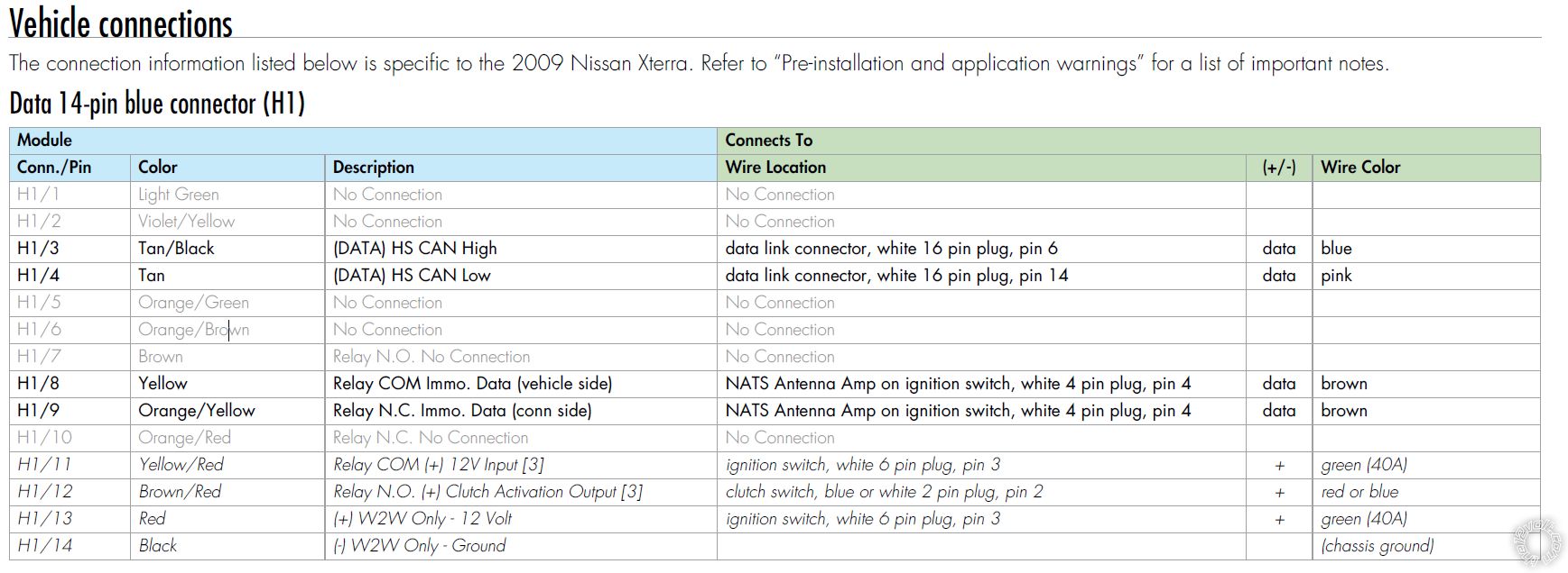
 Printable version


