the12volt.com spacer
icon

2009 Nissan Xterra, Viper 4806V Remote Start


Post ReplyPost New Topic
< Prev Topic Next Topic >
detergentcandy 
Member - Posts: 38
Member spacespace
Joined: March 13, 2021
Location: Colorado, United States
Posted: April 22, 2021 at 10:18 AM / IP Logged Link to Post Post Reply Quote detergentcandy
kreg357 wrote:
From the previous April 11th question, I would follow the diagram. The actual pin by pin info chart provided is very complete to cover all possible install types.
Diode use : If there are no wires in the indicated ARM and Disarm locations at the BCM connector, use the diodes and have the band towards the Viper 4806V controller. Try to Zip tie the diodes/Viper wires to an adjacent BCM wire to provide a secure and stable connection.
Thank you! What if there ARE wires in the Arm and Disarm locations?
If there are no wires, then I basically shove the diode into the socket like a pin?
kreg357 
Platinum - Posts: 7,783
Platinum spaceThis member has made a donation to the12volt.com. Click here for more info.spaceThis member has been recognized as an authority in Electrical Theory. Click here for more info.spaceThis member has been recognized as an authority in Mobile Security and Convenience. Click here for more info.spacespace
Joined: January 30, 2009
Location: Pennsylvania, United States
Posted: April 22, 2021 at 10:48 AM / IP Logged Link to Post Post Reply Quote kreg357
Yes, that is what the diodes are for, they fit pretty well into the socket for a decent electrical connection. Just secure them with a tie wrap to an adjacent wire as they can be easily pulled out. I usually tin the diode legs with some solder to provide a little extra thickness and grip. If there are wires in those locations, you can still use the diodes - they won't hurt anything.
Soldering is fun!
detergentcandy 
Member - Posts: 38
Member spacespace
Joined: March 13, 2021
Location: Colorado, United States
Posted: April 24, 2021 at 3:40 PM / IP Logged Link to Post Post Reply Quote detergentcandy
kreg357 wrote:
Accessory 2 power - the Viper 4806 can only supply 4 ignition type outputs ( ING1, Starter1, Starter2 and  ACC1. If the ACC2 is required you will need a relay. The DB3 install diagram shows  it connected.
I'm trying to figure out which of these wires I need to be connecting. Here's what the DB3 bypass diagram shows should be connected.
2009 Nissan Xterra, Viper 4806V Remote Start - Page 2 -- posted image.
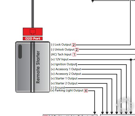
And here's the Viper wire connections list. I've added in red what I think some of them are supposed to be, but looks like I'm still missing ACC2 and Starter2.
2009 Nissan Xterra, Viper 4806V Remote Start - Page 2 -- posted image.
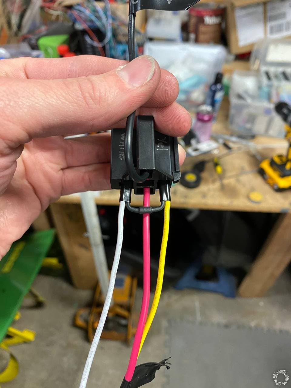
Now it does look like the Red/Black wire (12VDC Constant input for ACC and starter relays) is what I would connect to 86 and 87 on the relay, yes? Or is that incorrect because it says it's input, and I need to connect 86 and 87 to 12V output?
detergentcandy 
Member - Posts: 38
Member spacespace
Joined: March 13, 2021
Location: Colorado, United States
Posted: April 24, 2021 at 4:44 PM / IP Logged Link to Post Post Reply Quote detergentcandy
Good news today is I confirmed the trans neutral safety switch is (-) when in gear!
Neutral
2009 Nissan Xterra, Viper 4806V Remote Start - Page 2 -- posted image.
2nd
2009 Nissan Xterra, Viper 4806V Remote Start - Page 2 -- posted image.
So the only thing left I still need to figure out is the ACC2 and Starter2.
kreg357 
Platinum - Posts: 7,783
Platinum spaceThis member has made a donation to the12volt.com. Click here for more info.spaceThis member has been recognized as an authority in Electrical Theory. Click here for more info.spaceThis member has been recognized as an authority in Mobile Security and Convenience. Click here for more info.spacespace
Joined: January 30, 2009
Location: Pennsylvania, United States
Posted: April 24, 2021 at 5:39 PM / IP Logged Link to Post Post Reply Quote kreg357
Here are the connections for the 8 Pin ignition harness. It covers everything except the ACC2 wire.
Pin     Color              Function           connect to
1       Red/Black       +12V Input      +12V Constant
2       Pink/Black        87a    not used
3       Pink/White       Flex   Starter 2      *Program Viper Flex relay = Starter
4       Red +12V Input      +12V Constant
5       Violet Starter             Starter 1
6       Orange             ACC ACC1
7       Red/White    +12V Input       +12V Constant
8       Pink Ignition            Ignition
For the ACC2 wire, use the 30/40 Amp SPDT relay with inline fuse holder as follows :
Relay Pin 85 to Viper thin Orange wire labeled (-) Accessory Output
Relay Pin 86 and 87 to +12V constant through 25 Amp fuse
Relay Pin 30 to vehicle ACC2 wire
Relay Pin 87a not used - insulate
Soldering is fun!
detergentcandy 
Member - Posts: 38
Member spacespace
Joined: March 13, 2021
Location: Colorado, United States
Posted: April 24, 2021 at 11:34 PM / IP Logged Link to Post Post Reply Quote detergentcandy
2009 Nissan Xterra, Viper 4806V Remote Start - Page 2 -- posted image. Thanks Kreg!
kreg357 wrote:
3       Pink/White       Flex   Starter 2      *Program Viper Flex relay = Starter
Do I need to program the Viper with software? Or is this something I can program after install like you do when programing functions for the remote?
Didn't get as far as I wanted today but that's mostly cause I didn't know what to do with the 8 pin ignition harness. So I just sat around and organized tools. By the time I saw your answer it was a little too late to get back into it. But I made progress on the harnesses and the relay!
2009 Nissan Xterra, Viper 4806V Remote Start - Page 2 -- posted image.
Cathode side connects to 86, correct? I hope so :P
2009 Nissan Xterra, Viper 4806V Remote Start - Page 2 -- posted image.
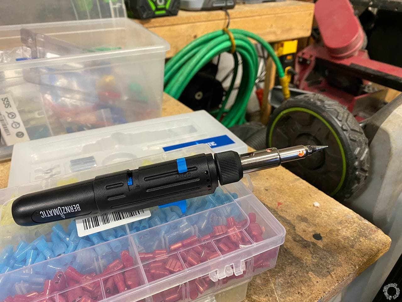
Also, I can't believe I've never owned a butane soldering iron until now. Makes soldering under a dash SO much easier when you don't have to worry about a cord.
2009 Nissan Xterra, Viper 4806V Remote Start - Page 2 -- posted image.
kreg357 
Platinum - Posts: 7,783
Platinum spaceThis member has made a donation to the12volt.com. Click here for more info.spaceThis member has been recognized as an authority in Electrical Theory. Click here for more info.spaceThis member has been recognized as an authority in Mobile Security and Convenience. Click here for more info.spacespace
Joined: January 30, 2009
Location: Pennsylvania, United States
Posted: April 25, 2021 at 3:25 AM / IP Logged Link to Post Post Reply Quote kreg357
Yes, the Flex Relay output ( Pink/White ) can be selected via Viper programming using the supplied remotes. See Menu 3, Feature 8, Option 3 for Starter2 output. There should be programming instructions in the 2 page Install Guide. It take a little practice to get used to using the remotes to make programming changes.
Yes, again, the diode Cathode ( stripe ) goes to Relay Pin 86 if you follow the above diagram and make Pin 86 the (+) side of the relay coil. Nice work on the relay socket wiring - very clean. 2009 Nissan Xterra, Viper 4806V Remote Start - Page 2 -- posted image.
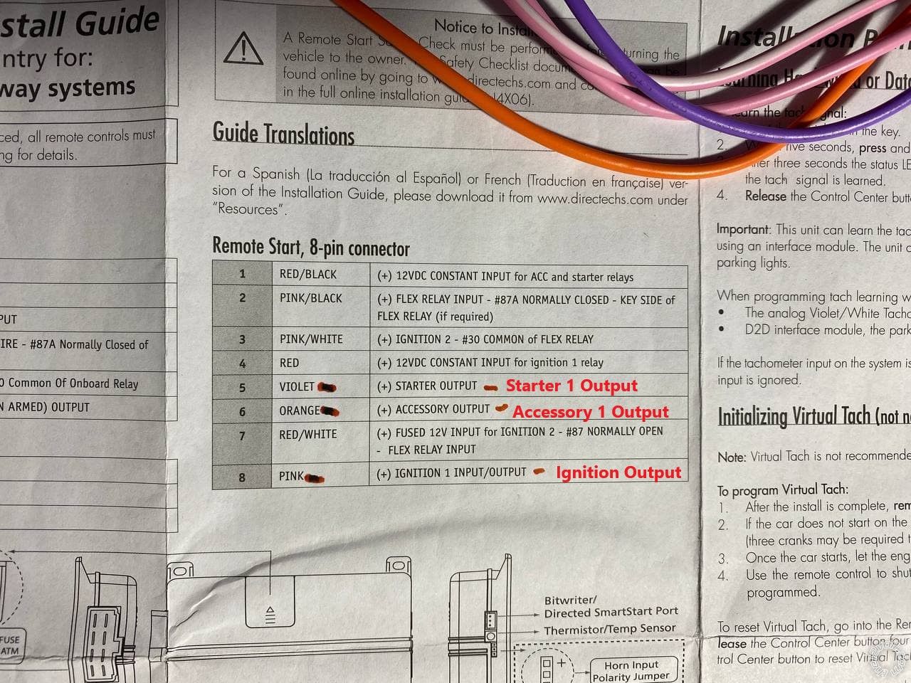
Looking at the 4806V Install Guide, the thin Orange (-) Accessory Output that goes to Relay Pin 85 is Pin 23 on the Aux/Shutdown 24 Pin harness. I'm sure you found that but just to clarify my earlier post.
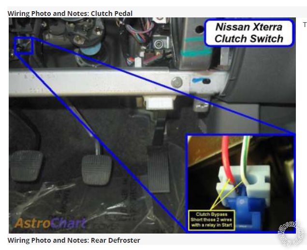
No cord on the soldering iron makes things easier. I couldn't find a butane iron that gave me the temp control I wanted so I'm still using a Hakko FX-601 soldering iron.
Soldering is fun!
detergentcandy 
Member - Posts: 38
Member spacespace
Joined: March 13, 2021
Location: Colorado, United States
Posted: April 26, 2021 at 3:01 AM / IP Logged Link to Post Post Reply Quote detergentcandy
I guess that's better than having to get the module programmed by a shop or distributor! I'll take a learning curve over that :P
And I do appreciate the clarification on the Acc. output.
Another question: the Parking Light Output on the remote start says it's only necessary if parking lights aren't supported in data. How can I find out if they're supported by data without installing everything first and trying it? I kept that wire long with the expectation that I would connect. But I can always trim it short if my lights are supported by data.
kreg357 
Platinum - Posts: 7,783
Platinum spaceThis member has made a donation to the12volt.com. Click here for more info.spaceThis member has been recognized as an authority in Electrical Theory. Click here for more info.spaceThis member has been recognized as an authority in Mobile Security and Convenience. Click here for more info.spacespace
Joined: January 30, 2009
Location: Pennsylvania, United States
Posted: April 26, 2021 at 6:06 AM / IP Logged Link to Post Post Reply Quote kreg357
Look at the DB3 Install Guide. There should be a list of supported D2D featured.   While I don't have a copy with me, From the wiring diagram you posted, it appears that Parking Lights are not supported via Data. The wiring diagram shows a (+) Parking Light output from the R/S controller that is directly connected to the vehicle. The exact vehicle wire should be listed in the DB3 Install Guide in the Harness connections section.
Soldering is fun!
detergentcandy 
Member - Posts: 38
Member spacespace
Joined: March 13, 2021
Location: Colorado, United States
Posted: April 26, 2021 at 8:24 PM / IP Logged Link to Post Post Reply Quote detergentcandy
Excellent! Found the parking lights in the kick panel and got those connected.
Can you explain the clutch wiring to me?
The DB3 instructions say to wire the clutch output to either 1 of the 2 clutch wires.
2009 Nissan Xterra, Viper 4806V Remote Start - Page 2 -- posted image.
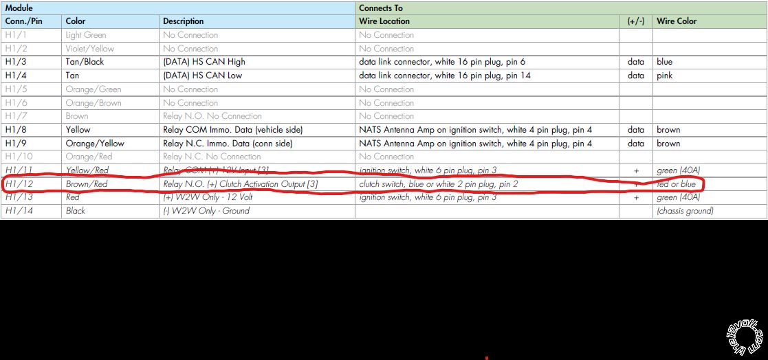
However, the Viper RS came with pictures of all the wire locations and in this picture it says to short both of the wires with a relay?
2009 Nissan Xterra, Viper 4806V Remote Start - Page 2 -- posted image.
Page of 6

  Printable version Printable version Post ReplyPost New Topic
You cannot post new topics in this forum
You cannot reply to topics in this forum
You cannot delete your posts in this forum
You cannot edit your posts in this forum
You cannot create polls in this forum
You cannot vote in polls in this forum

  •  
Search the12volt.com
Follow the12volt.com Follow the12volt.com on Facebook
Wednesday, April 24, 2024 • Copyright © 1999-2024 the12volt.com, All Rights Reserved Privacy Policy & Use of Cookies
Disclaimer: *All information on this site ( the12volt.com ) is provided "as is" without any warranty of any kind, either expressed or implied, including but not limited to fitness for a particular use. Any user assumes the entire risk as to the accuracy and use of this information. Please verify all wire colors and diagrams before applying any information.

Secured by Sectigo
the12volt.com spacer
Support the12volt.com
Top
the12volt.com spacer