the12volt.com spacer
icon

2009 Nissan Xterra, Viper 4806V Remote Start


Post ReplyPost New Topic
< Prev Topic Next Topic >
kreg357 
Platinum - Posts: 7,783
Platinum spaceThis member has made a donation to the12volt.com. Click here for more info.spaceThis member has been recognized as an authority in Electrical Theory. Click here for more info.spaceThis member has been recognized as an authority in Mobile Security and Convenience. Click here for more info.spacespace
Joined: January 30, 2009
Location: Pennsylvania, United States
Posted: April 26, 2021 at 9:44 PM / IP Logged Link to Post Post Reply Quote kreg357
Well, you could do it that way. That info is from an old AstroChart info/photo. The White/Green wire has +12V on it and when the clutch pedal is fully depressed the interlock switch closes and the +12V is supplied to the Red wire. By using a relay to do this "fully depressed" function you achieve the same thing during a remote start. You would use a signal like (-) Status Output to control/energize the relay. However, the DB3 makes it easier for you by supplying the +12V signal at the right time on its' H1/12 Red/Brown output wire. All you have to do is connect the Red/Brown wire to the non-White/Green wire in that 2 Pin Plug. As stated, the wire could be either Red or Blue. The photo has it shown in Red. So, find that 2 Pin plug at the clutch pedal with the White/Green wire and connect the DB3 Red/Brown wire to the other ( either Red or Blue ) wire in the 2 Pin Plug.
Soldering is fun!
detergentcandy 
Member - Posts: 38
Member spacespace
Joined: March 13, 2021
Location: Colorado, United States
Posted: April 27, 2021 at 1:39 AM / IP Logged Link to Post Post Reply Quote detergentcandy
2009 Nissan Xterra, Viper 4806V Remote Start - Page 3 -- posted image. I see why everyone says the bypass makes everything easier! Thanks for that info. Makes much more sense now.
Just need one more evening and I'll be done.
2009 Nissan Xterra, Viper 4806V Remote Start - Page 3 -- posted image.
For the bypass I still need to wire all the NATS, and the clutch.
The ignition harness was a massive PITA. I had maybe 3 inches of wire to work with? The solder wasn't the prettiest but it seemed strong and tape hides everything :P
2009 Nissan Xterra, Viper 4806V Remote Start - Page 3 -- posted image.
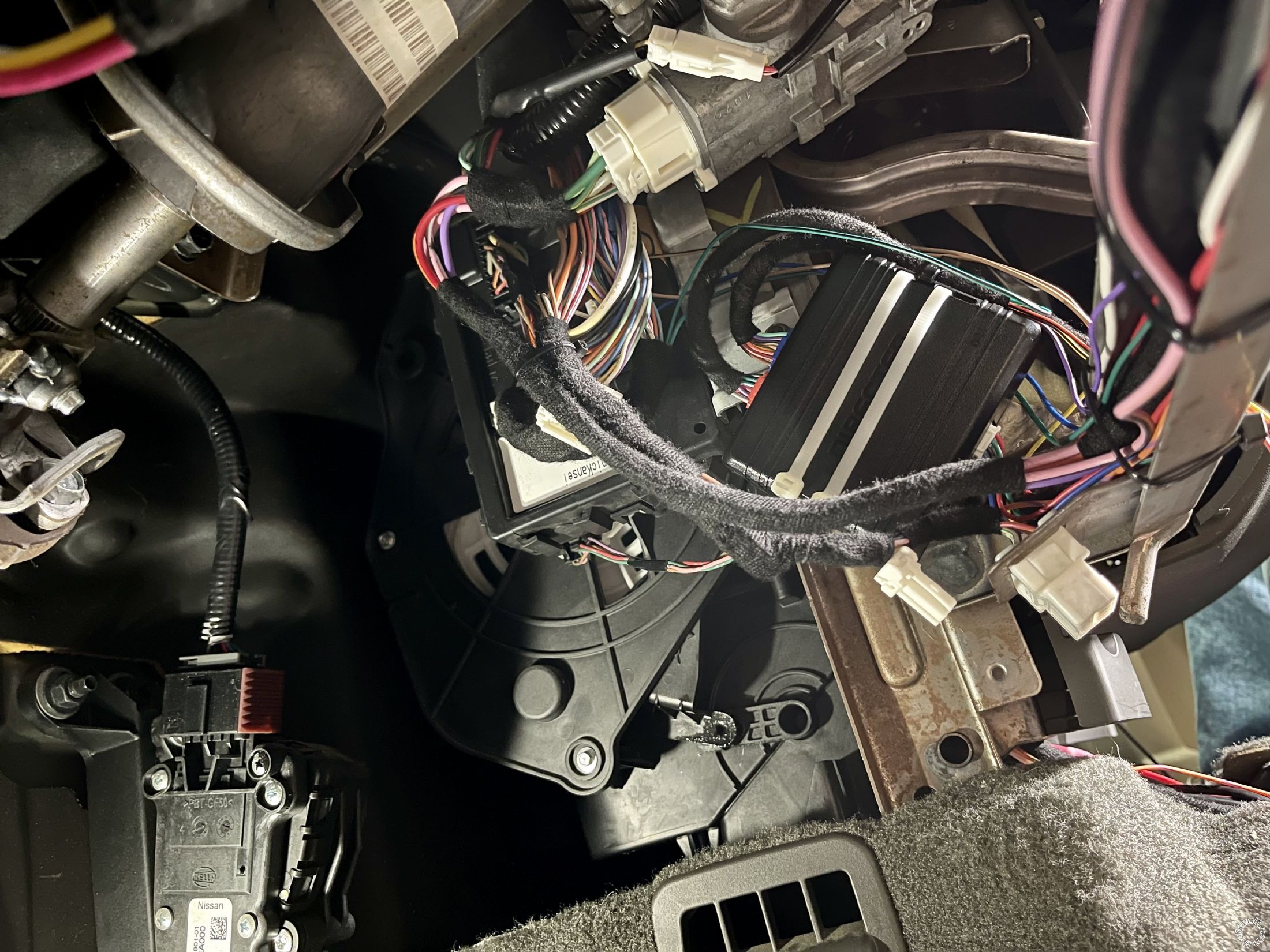
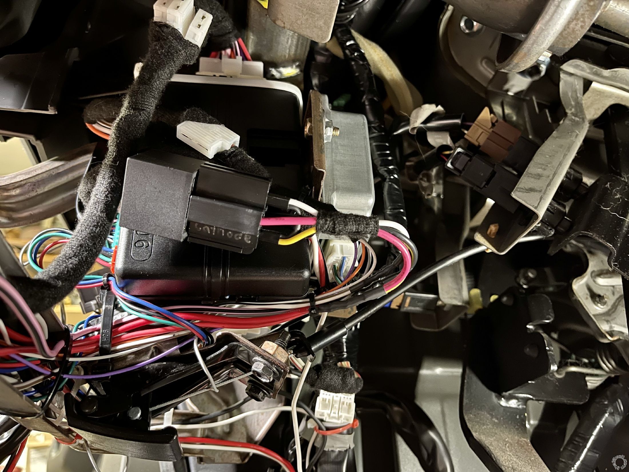
All that's left on the RS is the hood trigger. Didn't really know where to put the ACC2 relay so it's just zip tied to another harness. Not happy with that but it's close by in case anything needs to be replaced. Still need to wrap a lot of those wires in Tesa tape as well.
Other than the NATS, clutch, and hood, I just need to do the 12V wires.
Question: I have 3 wires from the RS that have in-line 20A fuses. Can I run all three of those to the same (+) lug on my fuse boxes and use a single 20A fuse? Should I use a 60A fuse? Or should I terminate each one at its own lug with 20A fuses at each? I have open lugs to do that but I also didn't plan on using half of them for this one install :P
kreg357 
Platinum - Posts: 7,783
Platinum spaceThis member has made a donation to the12volt.com. Click here for more info.spaceThis member has been recognized as an authority in Electrical Theory. Click here for more info.spaceThis member has been recognized as an authority in Mobile Security and Convenience. Click here for more info.spacespace
Joined: January 30, 2009
Location: Pennsylvania, United States
Posted: April 27, 2021 at 6:42 AM / IP Logged Link to Post Post Reply Quote kreg357
Only 3 power input wires from the Viper R/S system?
The Viper has H1/1 and from the R/S 8 Pin connector Red, Red/White and Red/Black. Add in the 20 Amp fused input to the external ACC2 relay and you have 5 wires needing +12V power. Viper H1/1 supplies power to the Viper controller logic, the (+) Parking Light output and the bypass module.
At the vehicles ignition switch, the Dark Green wire supplies power to all of the ignition wires and is rated/fused at 40 amps.
I think I would split and balance the 5 input power wires between two of your open power lugs, both fused at 40 Amps. Or you could use the vehicles Dark Green wire at the ignition switch connector as one source and save a power lug.
Soldering is fun!
detergentcandy 
Member - Posts: 38
Member spacespace
Joined: March 13, 2021
Location: Colorado, United States
Posted: April 27, 2021 at 12:33 PM / IP Logged Link to Post Post Reply Quote detergentcandy
Yes, correct! Sorry for the late night confusion!
I have:
3 power from the R/S 8 pin connector
1 power from the relay (86 and 87) -------|
1 power from the R/S 6 pin connector ---|---- connected together into 1 power
1 power from the bypass --------------------|
I hope that makes sense? I spliced the bottom 3 together so I only actually have 4 power wires in total that need to be connected.
The R/S has 2 jumpers. The first one is for the "light flash polarity". I assume since my parking lights are (+), I jumper that one (+)?
The other is "horn input polarity jumper." I'm not connecting a horn wire, so is this something I need to worry about?
kreg357 
Platinum - Posts: 7,783
Platinum spaceThis member has made a donation to the12volt.com. Click here for more info.spaceThis member has been recognized as an authority in Electrical Theory. Click here for more info.spaceThis member has been recognized as an authority in Mobile Security and Convenience. Click here for more info.spacespace
Joined: January 30, 2009
Location: Pennsylvania, United States
Posted: April 27, 2021 at 1:09 PM / IP Logged Link to Post Post Reply Quote kreg357
Good plan with the +12V input power. You could connect the 3 R/S 8 Pin power inputs to one power lug and fuse at 40 amps.
Yes, your vehicle needs (+) Parking Lights so make sure that fuse/jumper is set to (+).
The Horn polarity jumper doesn't matter if you don't plan to connect that Blue wire and use the Horn Alert feature.
Soldering is fun!
detergentcandy 
Member - Posts: 38
Member spacespace
Joined: March 13, 2021
Location: Colorado, United States
Posted: April 27, 2021 at 2:50 PM / IP Logged Link to Post Post Reply Quote detergentcandy
Hmm, I guess the question is will the horn still honk when the doors are locked like factory? I don't really care if the horn honks when the car is remote started, but I like the audible confirmation of locking the doors so I don't have to look back at the car and confirm it's locked in a parking lot.
kreg357 
Platinum - Posts: 7,783
Platinum spaceThis member has made a donation to the12volt.com. Click here for more info.spaceThis member has been recognized as an authority in Electrical Theory. Click here for more info.spaceThis member has been recognized as an authority in Mobile Security and Convenience. Click here for more info.spacespace
Joined: January 30, 2009
Location: Pennsylvania, United States
Posted: April 27, 2021 at 4:00 PM / IP Logged Link to Post Post Reply Quote kreg357
The horn confirmation beeps come for the H1/3 Brown (-) Horn Output wire.
Info on vehicles horn wire: Horn   BROWN OR RED (-)   HORN SWITCH OR DRIVER KICK PANEL in WHITE 16 PIN CONN, PIN 9
Direct connection should be fine.
Soldering is fun!
detergentcandy 
Member - Posts: 38
Member spacespace
Joined: March 13, 2021
Location: Colorado, United States
Posted: April 29, 2021 at 3:03 PM / IP Logged Link to Post Post Reply Quote detergentcandy
Got that reextended after initially cutting it short, haha. Good to go there!
There is an orange wire on the same harness that is GWA (ground when armed). I didn't initially have this connected cause the DB3 diagram didn't mention it. Is that necessary?
UPDATE: according to this thread (https://www.the12volt.com/installbay/forum_posts.asp?tid=102418) I don't need the GWA wire.
detergentcandy 
Member - Posts: 38
Member spacespace
Joined: March 13, 2021
Location: Colorado, United States
Posted: April 30, 2021 at 12:12 AM / IP Logged Link to Post Post Reply Quote detergentcandy
kreg357 wrote:
The horn confirmation beeps come for the H1/3 Brown (-) Horn Output wire.
Info on vehicles horn wire: Horn   BROWN OR RED (-)   HORN SWITCH OR DRIVER KICK PANEL in WHITE 16 PIN CONN, PIN 9
Direct connection should be fine.
Done and done!
Wrapped up the install tonight and I was partially successful.
DB3 programmed successfully.
Tach learn programmed successfully.
Key fob locks and unlocks doors.
When attempting to remote start, I get several parking light flashes in pretty quick succession, then nothing, then 5 slow parking light flashes, and that's it. I believe this is the "Brake wire is active" error. Any ideas? I reconfirmed that the black/white parking/e-brake input that I have connected to the transmission neutral safety switch is closed when the transmission is in neutral and open when in gear. So that seems to be working as I expected. But not sure why I'm getting the error...
kreg357 
Platinum - Posts: 7,783
Platinum spaceThis member has made a donation to the12volt.com. Click here for more info.spaceThis member has been recognized as an authority in Electrical Theory. Click here for more info.spaceThis member has been recognized as an authority in Mobile Security and Convenience. Click here for more info.spacespace
Joined: January 30, 2009
Location: Pennsylvania, United States
Posted: April 30, 2021 at 8:33 AM / IP Logged Link to Post Post Reply Quote kreg357
Well, according to the DB3 install guide, the DB3 supplies the Brake signal via the DBI D2D harness. Not much you can do there to test things.
At this point there are many possible issues.
The clutch bypass might not be working. You could a try a R/S while sitting in the vehicle with the clutch pedal depressed.
You could try a a R/S while a key was inserted but not turned in the ignition switch.
You could try a R/S with the Viper EBrake/Neutral Safety wire disconnected (and the transmission in neutral!).
You should preform the Viper Shutdown Diagnostics on it to see exactly which code is present. The steps are outlined in the 2 page Viper install guide. This will give you a better starting point.
Soldering is fun!
Page of 6

  Printable version Printable version Post ReplyPost New Topic
You cannot post new topics in this forum
You cannot reply to topics in this forum
You cannot delete your posts in this forum
You cannot edit your posts in this forum
You cannot create polls in this forum
You cannot vote in polls in this forum

  •  
Search the12volt.com
Follow the12volt.com Follow the12volt.com on Facebook
Friday, April 26, 2024 • Copyright © 1999-2024 the12volt.com, All Rights Reserved Privacy Policy & Use of Cookies
Disclaimer: *All information on this site ( the12volt.com ) is provided "as is" without any warranty of any kind, either expressed or implied, including but not limited to fitness for a particular use. Any user assumes the entire risk as to the accuracy and use of this information. Please verify all wire colors and diagrams before applying any information.

Secured by Sectigo
the12volt.com spacer
Support the12volt.com
Top
the12volt.com spacer