what wires i only need for this install?
There will be many wires needed for this install. You have chosen to install a remote starter on a manual transmission vehicle. This requires more wires. While the Viper 4806 is a manual transmission safe platform, it requires many additional things to be safely installed on a manual transmission vehicle.
Here is a list :
1. The Viper must be run in Tach Mode. This will require a hardwired Tach connection and a successful Tach Learn before the first remote start.
2. Even though the 4806 is not an Alarm system, the Door and Rear Hatch input wires must be properly connected to the car to allow entry into Reservation Mode.
3. Same goes for the vehicles Parking Brake. It must be connected to the Viper as it is also used to enter into Reservation Mode.
4. The final extra piece of the puzzle is the Clutch Pedal. It must be bypassed to allow the starter motor to crank the engine.
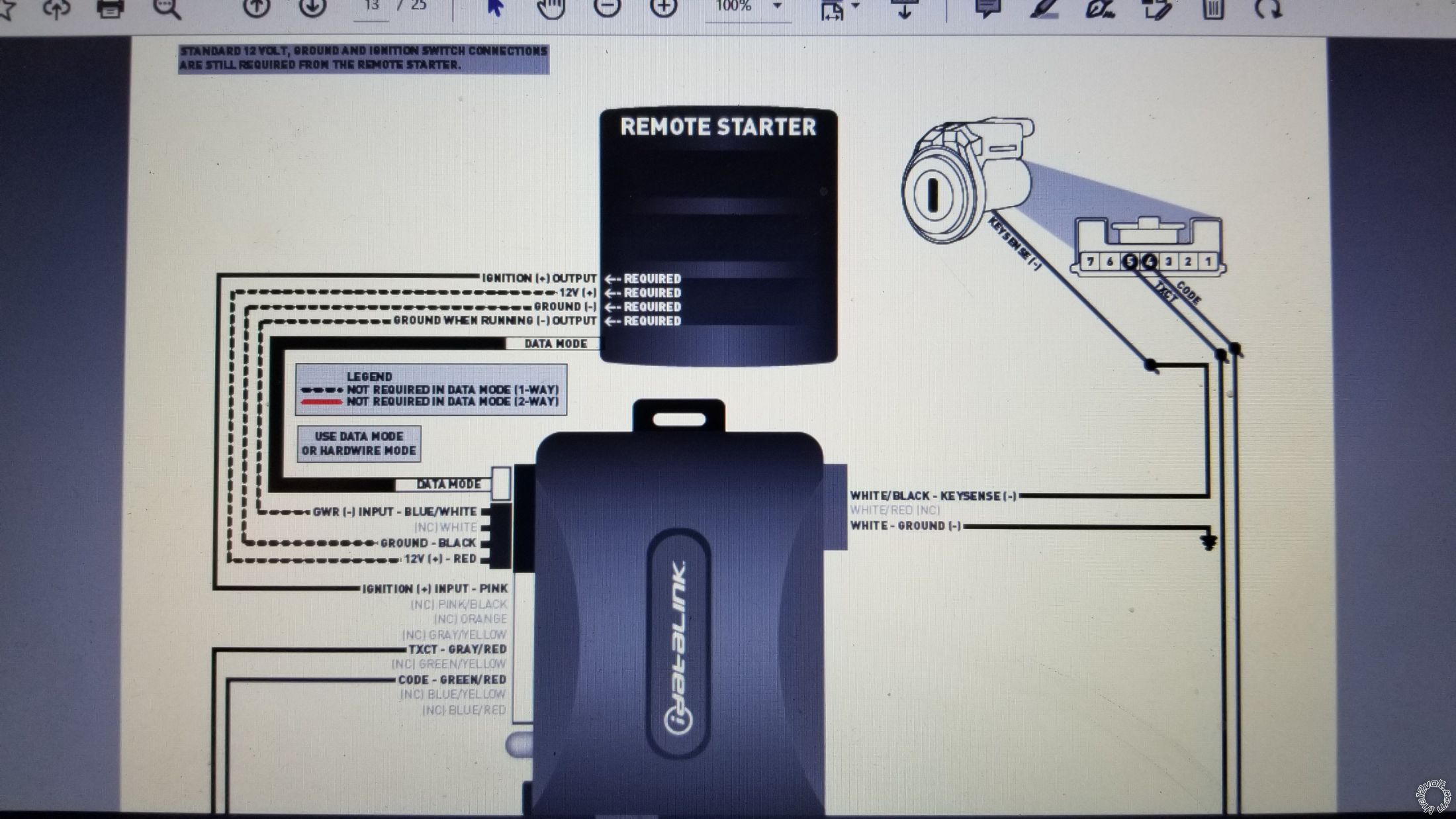
and what does the dashed line means on the bypass module, that's what confuses me a lot.
The ADS TB bypass module is used to bypass the vehicles transponder based immobilizer system. The three dashed lines are required in W2W mode. If you run the ADS TB in D2D mode they are not necessary because their function is handled by the 4 Pin Data harness connection between the Viper and the ADS TB. Of course there is a big note on the ADS TB. First, it must be flashed with the correct firmware to support your Toyota. This firmware comes in two flavors, ADS and DBI. You should flash the DBI version onto the ADS TB module to allow two way D2D communications and use the 4 Pin Data Harness. So DBI TB DL is the preferred firmware for your specific application. Second, you must set the Installation Mode to DATA prior to vehicle programming. The steps are in the DBI TB TL Guide #77711.
I would suggest listing your proposed vehicle wire connections for this install so that
the Forum members can review them and provide any needed corrections. To help, here is
a text harness list for your 4806 :
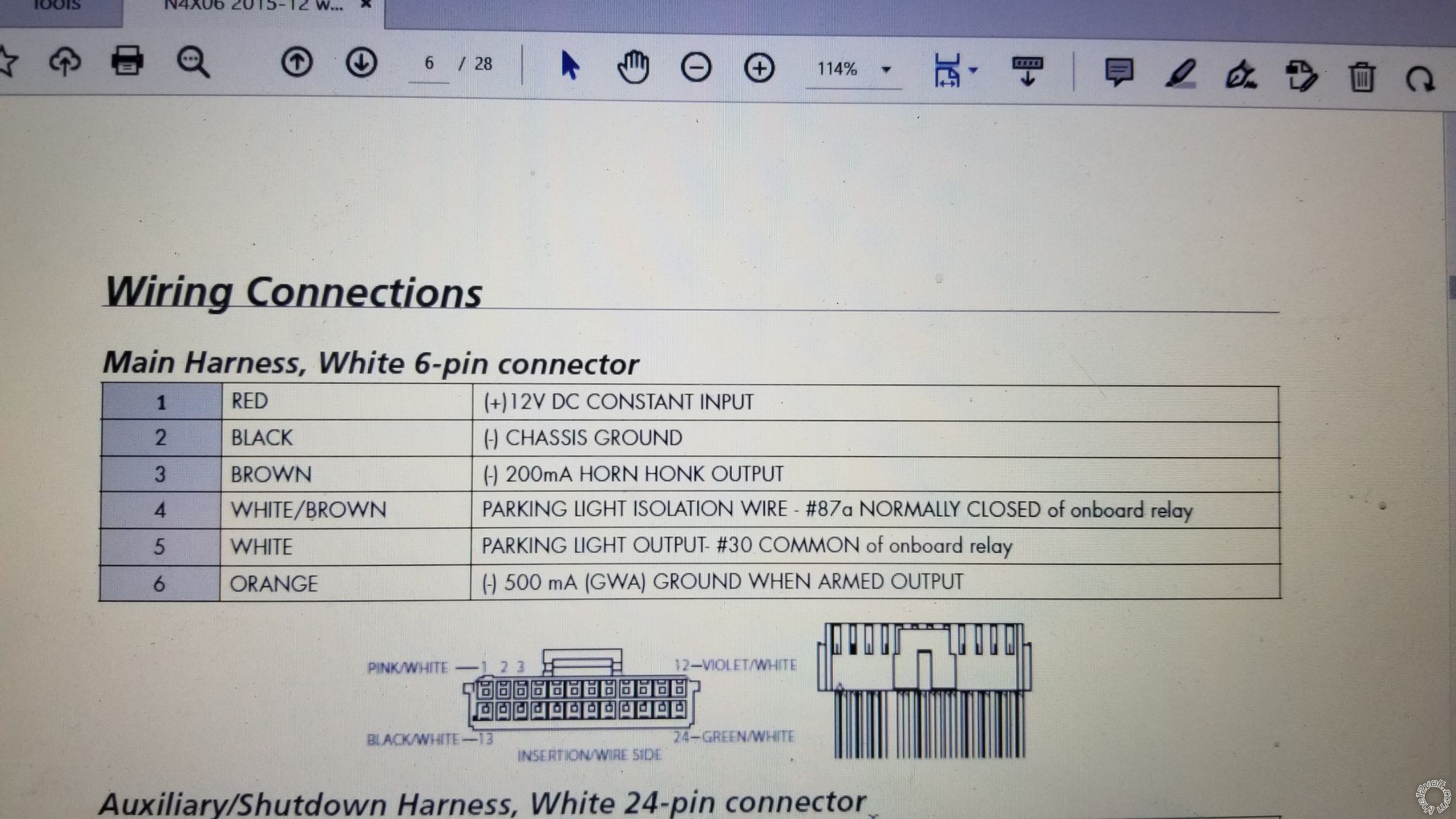
H/1 RED (+)12VDC CONSTANT INPUT *
H/2 BLACK (-) CHASSIS GROUND *
H/3 BROWN (-) 200mA HORN HONK OUTPUT
H/4 WHITE/BROWN LIGHT FLASH ISOLATION WIRE
H/5 WHITE PIN 30 of LIGHT FLASH RELAY jumper selectable *
H/6 ORANGE 500 mA GROUND WHEN ARMED OUTPUT
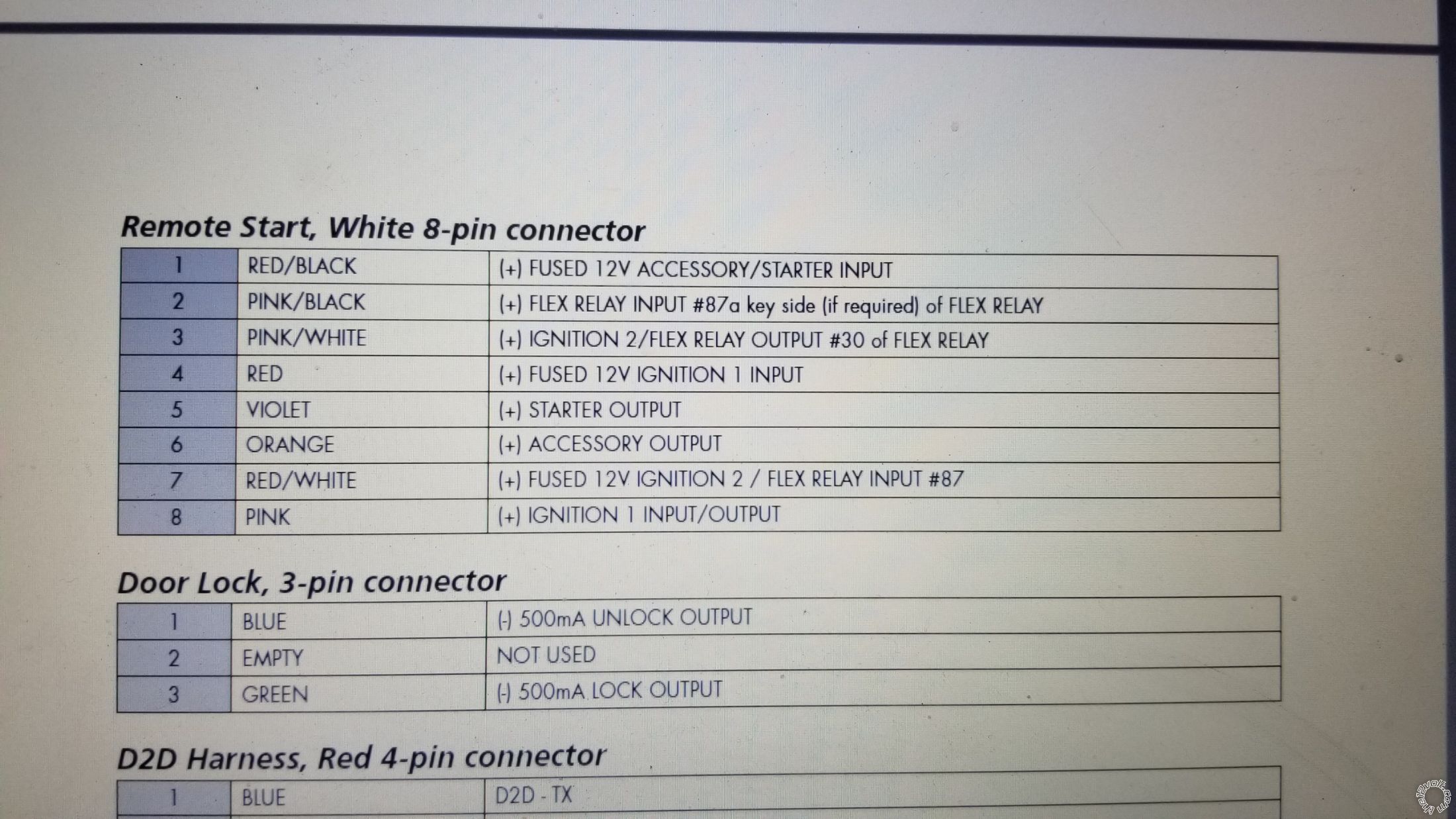
Remote Start, 8-pin connector
1 RED/BLACK (+) 12VDC CONSTANT INPUT *
2 PINK/BLACK (+) FLEX RELAY INPUT 87A
3 PINK/WHITE (+) IGNITION 2 set to IGN2 *
4 RED (+) 12VDC CONSTANT INPUT *
5 VIOLET (+) STARTER OUTPUT *
6 ORANGE (+) ACCESSORY OUTPUT *
7 RED/WHITE (+) 12VDC CONSTANT INPUT *
8 PINK (+) IGNITION 1 INPUT/OUTPUT *
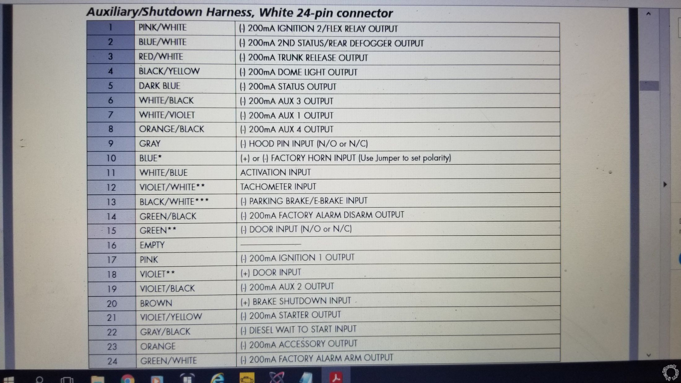
Auxiliary/Shutdown Harness 24-pin connector
1 PNK/WHITE (-) 200mA Ignition 2/Flex OUTPUT
2 BLUE/WHITE (-) 200mA 2ND STATUS /REAR DEFOGGER OUTPUT
3 RED/WHITE (-) 200mA TRUNK RELEASE OUTPUT *
4 BLACK/YELLOW (-) 200mA DOME LIGHT OUTPUT
5 DARK BLUE (-) 200mA STATUS OUTPUT
6 WHITE/BLACK (-) 200mA AUX 3 OUTPUT
7 WHITE/VIOLET (-) 200mA AUX 1 OUTPUT
8 ORANGE/BLACK (-) 200mA AUX 4 OUTPUT
9 GRAY (-) HOOD PIN INPUT (NC OR NO) *
10 BLUE FACTORY HORN INPUT (Use Jumper to set polarity)
11 WHITE/BLUE ACTIVATION INPUT
12 VIOLET/WHITE TACHOMETER INPUT *
13 BLACK/WHITE (-) NEUTRAL SAFETY / PARKING BRAKE INPUT *
14 GREEN/BLACK (-) 200mA FACTORY ALARM DISARM OUTPUT
15 GREEN (-) DOOR INPUT *
16 EMPTY ------------------------------------
17 PINK (-) 200mA IGNITION 1 OUTPUT
18 VIOLET (+) DOOR INPUT
19 VIOLET/BLACK (-) 200mA AUX 2 OUTPUT
20 BROWN (+) BRAKE SHUTDOWN INPUT *
21 VIOLET/YELLOW (-) 200mA STARTER OUTPUT
22 GRAY/BLACK (-) DIESEL WAIT TO START INPUT
23 ORANGE (-) 200mA ACCESSORY OUTPUT
24 GREEN/WHITE (-) 200mA FACTORY ALARM ARM OUTPUT
* = necessary
Soldering is fun!


 what wires i only need for this install?
and what does the dashed line means on the bypass module, that's what confuses me a lot.
thank you in advance
what wires i only need for this install?
and what does the dashed line means on the bypass module, that's what confuses me a lot.
thank you in advance


 Do you have the necessary diodes for the Door / Rear Hatch trigger inputs and a relay for the Clutch Bypass during a R/S?
 Printable version


