the12volt.com spacer
icon

Viper 5906V Door Lock Pulse


Post ReplyPost New Topic
< Prev Topic Next Topic >
sgo70 
Member - Posts: 18
Member spacespace
Joined: June 30, 2021
Location: Alberta, Canada
Posted: February 19, 2022 at 9:13 AM / IP Logged Link to Post Post Reply Quote sgo70
Hello, I'm doing a frame up build and engine swap on a Land Rover Defender and I have installed power door locks using the 2 relay negative pulse method and Dakota Digital Actuators and everything works great. The problem I'm having is the door remote from the Viper 5906v system. I was told by tech support that it is a neg pulse but I think I have found out that one wire will pulse negative and the other will pulse 12v+. I'm trying to figure out how I would wire this in, I'm stumped.
2 Relays:
12v+ to post 86 and 87
Ground to 87A
Actuator to 30
Carling Switch ground to 85
I appreciate the help, I have a pretty good understanding of electrical basics but I'm no wizard.
Thanks
geepherder 
Platinum - Posts: 3,668
Platinum spaceThis member consistently provides reliable informationspace
Joined: October 27, 2003
Posted: February 19, 2022 at 4:06 PM / IP Logged Link to Post Post Reply Quote geepherder
I think it was only the older models that pulsed negative one way, positive the other. Either way it doesn't matter. You're over thinking it. If one side of the relay coil is positive 12 volts, and you apply 12 volts to the other side, nothing happens. It'll only trigger on a negative pulse. Just do this:
https://www.the12volt.com/relays/relaydiagram75.html
My ex once told me I have a perfect face for radio.
sgo70 
Member - Posts: 18
Member spacespace
Joined: June 30, 2021
Location: Alberta, Canada
Posted: February 20, 2022 at 8:42 AM / IP Logged Link to Post Post Reply Quote sgo70
Ok thanks, that's pretty much what I have except I ran the 12 V+ to both 86 terminals and the switches to 85. Does that make a difference?
When I plug into the alarm unit and try the locks it blows the fuse, sometimes I'll get it to work once then the next try blows the fuse, I guess that's why I thought it was pulsing 12v+ on the other side. I put my test light on it to see and I'm not getting it to light, not sure if it's because it's too small of a load or too quick or maybe you're right and it doesn't pulse positive.
If I wired the green and white switch legs backwards it would just operate backwards, am I right on this? Not sure what else this could be, should be so easy.
Thank You,
sgo70 
Member - Posts: 18
Member spacespace
Joined: June 30, 2021
Location: Alberta, Canada
Posted: February 20, 2022 at 9:54 AM / IP Logged Link to Post Post Reply Quote sgo70
Okay, I tried a few more things. When I touch a ground probe to the Viper connector the doors lock/unlock as they should so I think my wiring is okay except maybe I have them reversed.
When I use the FOB it says a door is open and it chatters until I unplug the connector.
I made sure all my door jamb switches were pressed in (ground when doors open) and now the key FOB will lock the doors when I hit unlock (wires reversed I figure) but they will not unlock and they key FOB says a door is open. I'm assuming they won't unlock (which the Viper thinks is locking) because it senses a door open. I'll swap the wires to see what happens.
Another thing is I don't have my interior dome lights in yet (waiting for connectors). They get a constant power and then one ground wire to the door jambs and another to a switch. Could this cause a problem with the door locks? I tapped the Viper into the ground wire coming off the door jamb switch, getting frustrated now lol.
geepherder 
Platinum - Posts: 3,668
Platinum spaceThis member consistently provides reliable informationspace
Joined: October 27, 2003
Posted: February 21, 2022 at 10:43 AM / IP Logged Link to Post Post Reply Quote geepherder
Sorry, I'm getting senile in my old age. I re-read your original post and realized you already added a power door lock system complete with switches that works properly. Now you want to add the keyless entry functionality. Unless you have diodes installed across the relay coils, 85 and 86 will be interchangeable. A test light may take too long to illuminate that it wouldn't show anything. A multimeter might give you a better indicator. My digital meters will sometimes just flash "OL" when testing pulses. An analog meter would likely give you a needle deflection which would be more noticeable.
I'm not sure which fuse you are referring to that is blowing- one you installed for the door locks or one on the Viper.
Yes, if wired backwards it should just work in reverse. I'm assuming you mean the blue wire, not the white wire.
The likely fix for your door trigger is to use diodes and combine each of the switch outputs (from the switches themselves) instead of the wire at the dome light. The BCM is likely powering the dome light when you unlock, causing the false trigger.
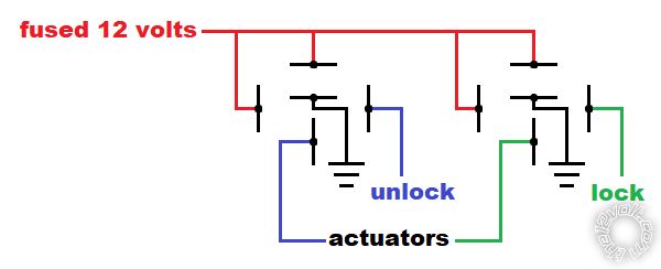
All you should need to do is connect the Viper's unlock output to the existing unlock wire of the system and do the same with the lock output. This is assuming it's connected as described in your original post. It should look something like this: Viper 5906V Door Lock Pulse -- posted image.
Try this and let us know if you need anymore help.
My ex once told me I have a perfect face for radio.
sgo70 
Member - Posts: 18
Member spacespace
Joined: June 30, 2021
Location: Alberta, Canada
Posted: February 21, 2022 at 4:31 PM / IP Logged Link to Post Post Reply Quote sgo70
Wow thanks for the explanation, I was standing by the fuel tank with a lighter lol.
I just verified I have diodes in my relays, they're actually 35amp micro relays, 280 series I think they're called. So I'm guessing I'll have to swap 85 and 86 back on the lock side since I switched the wires and it will now unlock but not lock.
Yes it was my fuse I have in the panel for the locks, that's not blowing any more, I read I need 7.5 amps/actuator so against my better judgement I went to a 30 amp fuse.
Yes I have it tapped into the switch wires and I did find one dumb mistake which I fixed, I had all my door jamb switches wired together then to the ground bar. Kinda explains why it kept saying a door was open....should've clicked seeing a blue wire going to ground.
I tried putting the meter on the Viper and when I use the FOB it looks like I'm getting a reading but it is quick, I'm going to try and phone them to confirm it does send out 12v+ as well. So another question I'm not sure of, if I put diodes on (the right way), it will block the 12v+ out but will it allow the negative pulse through?
I won't even get into my other problems, remote start not available and can't do the tach learn haha, this is getting exhausting.
I really appreciate the help, thank you,
Sean
sgo70 
Member - Posts: 18
Member spacespace
Joined: June 30, 2021
Location: Alberta, Canada
Posted: February 21, 2022 at 4:41 PM / IP Logged Link to Post Post Reply Quote sgo70
Actually, just thinking about it, if the door locks work fine with the switches and I have it wired up as you show above, can I just leave the relays alone? I'm wondering if the switch is overpowering the diode in the relay but maybe the Viper isn't, sorry if that's a dumb question. So to be clear:
Switch works good both lock/unlock
Viper with remote unlock with FOB
Viper will not lock with FOB
Dome light supervision wire is now disconnected
Viper is wired into switch wires
and I'm losing my mind lol.
sgo70 
Member - Posts: 18
Member spacespace
Joined: June 30, 2021
Location: Alberta, Canada
Posted: February 21, 2022 at 5:30 PM / IP Logged Link to Post Post Reply Quote sgo70
I switched the relays around, no change, still won't lock with the FOB. Viper was closed, I'll have to call tomorrow and go get a couple diodes.
geepherder 
Platinum - Posts: 3,668
Platinum spaceThis member consistently provides reliable informationspace
Joined: October 27, 2003
Posted: February 22, 2022 at 4:40 PM / IP Logged Link to Post Post Reply Quote geepherder
So, the 7.5 amp fuse, was this factory, or is this part of the harness you added for the door locks? If it's a factory fuse location, you should use a separate power source, as anything higher will overload the factory wiring. Your door locks probably draw 20 amps or more, so a 25 or 30 amp fuse is probably about right. That said, the wiring needs to be capable of safely handling that.
Just to clarify, your current setup uses two relays to work with the switches, similar to the diagram I posted, correct? You could verify your door locks are programmed to the .8 second pulse duration (should be default) and not .4 second. You could also verify output with a separate relay. Just connect 12 volts to 86 and the Viper door lock output wire to 85. The activate it with the remote. Did your relay click? Do the same with unlock.
Diodes installed across the coil are not meant to block signal in the sense you are thinking, but to prolong relay life.
My ex once told me I have a perfect face for radio.
sgo70 
Member - Posts: 18
Member spacespace
Joined: June 30, 2021
Location: Alberta, Canada
Posted: February 22, 2022 at 7:04 PM / IP Logged Link to Post Post Reply Quote sgo70
It's all my own wiring, 12 g GXL to all the actuators and 14 g to all the switches. The 2 relays are fed power to their own 30 amp fuse location in the fuse panel. I tend to overdo the wiring so I'm confident it'll be good lol.
I actually got a hold of a tech support guy at Viper and he confirmed only an 800milliamp negative pulse, no 12v+. He actually told me to test with a relay just as you did and it wasn't good. The unlock clicked but the lock side was dead. I think because I didn't have any diodes protecting the Viper box it might have gotten cooked when I tested out the switches, he seemed to agree. So looks like I have to chalk this up to the price of learning and get a new box. On the plus side when I called them to see if I can just order the control box the lady on the other end said she was going to try to warranty it for me, worth a try, really nice of her.
I found this document from Viper that shows exactly what I have, Type D after-market actuators, I find it odd they don't make mention of using any diodes but when I talked to him he said I should. I guess I'll add them in while I wait.
https://pdf.ampire.de/directed/Tech-Tip-1041.pdf
Thanks again,
Sean
Page of 3

  Printable version Printable version Post ReplyPost New Topic
You cannot post new topics in this forum
You cannot reply to topics in this forum
You cannot delete your posts in this forum
You cannot edit your posts in this forum
You cannot create polls in this forum
You cannot vote in polls in this forum

  •  
Search the12volt.com
Follow the12volt.com Follow the12volt.com on Facebook
Saturday, April 20, 2024 • Copyright © 1999-2024 the12volt.com, All Rights Reserved Privacy Policy & Use of Cookies
Disclaimer: *All information on this site ( the12volt.com ) is provided "as is" without any warranty of any kind, either expressed or implied, including but not limited to fitness for a particular use. Any user assumes the entire risk as to the accuracy and use of this information. Please verify all wire colors and diagrams before applying any information.

Secured by Sectigo
the12volt.com spacer
Support the12volt.com
Top
the12volt.com spacer