the12volt.com spacer
icon

2005 colbalt alarm/remote start wiring


Post ReplyPost New Topic
< Prev Topic Next Topic >
j68rh 
Copper - Posts: 147
Copper spacespace
Joined: March 31, 2005
Location: United States
Posted: July 04, 2005 at 8:23 PM / IP Logged  
I plan on doing that.  Tomorrow I am takeing the system out and seeing if the problem is still there if it is or not I am going to tell the person to take the car in for a diagnostic.  Just to verify.  The bypass module I used is the one from DEI.  I stuck one of those home computer diagnostic computers on and it would not link with the cars computer.  I think the Remote start shorted out the cars computer.  I will now more tomorrow
j68rh 
Copper - Posts: 147
Copper spacespace
Joined: March 31, 2005
Location: United States
Posted: July 05, 2005 at 2:05 PM / IP Logged  
Alright, my start wire is yellow.  My to ignition wires are brown and my ACC wire is Blue.  this is comeing off the remote start module.  from looking at the wire diagram and the direct fax document 1610 how would I hook this up????
j68rh 
Copper - Posts: 147
Copper spacespace
Joined: March 31, 2005
Location: United States
Posted: July 06, 2005 at 9:19 AM / IP Logged  

Velocity Motors wrote:
j68rh, use the PLXR bypass module from bypasskits. This is the module that we use for all the ION type passlock systems and it works great. If your having problems with the system I suggest removing the bypass relays and see if your problems are still there.

Velocitymotors,

I was wondering according to the diagram and my wire colors on the remote start.  My starter wire is Yellow my 2 ignition wires are brown and my ACC wire is blue.  And on the document 1610 I took the pink wire like it said and hooked it up to the one ignition wire but where do the other wires go on this thing? 

Velocity Motors 
Moderator - Posts: 12,488
Moderator spaceThis member has made a donation to the12volt.com. Click here for more info.spaceThis member has been recognized as an authority in Electrical Theory. Click here for more info.spaceThis member has been recognized as an authority in Fabrication. Click here for more info.spaceThis member has been recognized as an authority in Mobile Audio and Video. Click here for more info.spaceThis member has been recognized as an authority in Mobile Security and Convenience. Click here for more info.spacespace
Joined: March 08, 2002
Location: Manitoba, Canada
Posted: July 06, 2005 at 11:12 AM / IP Logged  

There is a white wire and a WHITE/ black wire at the ignition harness that performs the following: key sense, second ignition, starter, and Passlock resistance. You do not need to hook up a starter wire for these types of systems.When accessory shuts down during the start cycle the vehicle will crank automatically. Here are the wires that you have for the Cobalt:

  12 VOLTS
RED / black ----- C3 plug on BCM in center console * THE BCM is located in the passenger side of the center console. It has 4 plug running left to right C1 (72-pin), C2(72-pin), C3(40-pin) & C4 (not used).
 
IGNITION
Yellow ---- Ignition switch harness or C4 plug on BCM *THE BCM is located in the passenger side of the center console. It has 4 plug running left to right C1 (72-pin), C2(72-pin), C3(40-pin) & C4 (not used).
 
ACCESSORY
Brown ------ Ignition switch harness or C4 plug on BCM  *THE BCM is located in the passenger side of the center console. It has 4 plug running left to right C1 (72-pin), C2(72-pin), C3(40-pin) & C4 (not used).
Remember that the instructions that are labelled on the 555L are generic for the Saturn Ion and does not necessarily pertain to the Cobalt. If you are using the 555L for your vehicle, take the information for the wire description and not the wire color.

Jeff
Velocity Custom Home Theater
Mobile Audio/Video Specialist
Morden, Manitoba CANADA
j68rh 
Copper - Posts: 147
Copper spacespace
Joined: March 31, 2005
Location: United States
Posted: July 06, 2005 at 2:43 PM / IP Logged  
Velocity Motors wrote:

There is a white wire and a WHITE/ black wire at the ignition harness that performs the following: key sense, second ignition, starter, and Passlock resistance. You do not need to hook up a starter wire for these types of systems.When accessory shuts down during the start cycle the vehicle will crank automatically. Here are the wires that you have for the Cobalt:

  12 VOLTS
RED / black ----- C3 plug on BCM in center console * THE BCM is located in the passenger side of the center console. It has 4 plug running left to right C1 (72-pin), C2(72-pin), C3(40-pin) & C4 (not used).
 
IGNITION
Yellow ---- Ignition switch harness or C4 plug on BCM *THE BCM is located in the passenger side of the center console. It has 4 plug running left to right C1 (72-pin), C2(72-pin), C3(40-pin) & C4 (not used).
 
ACCESSORY
Brown ------ Ignition switch harness or C4 plug on BCM  *THE BCM is located in the passenger side of the center console. It has 4 plug running left to right C1 (72-pin), C2(72-pin), C3(40-pin) & C4 (not used).
Remember that the instructions that are labelled on the 555L are generic for the Saturn Ion and does not necessarily pertain to the Cobalt. If you are using the 555L for your vehicle, take the information for the wire description and not the wire color.

So let me get this straight the brown wire  Is the C4 plug well C4 isn't that on the right side? or is it also on the passanger side?  So my blue ACC (blue from the remote start wire) goes to this brown Ignition or does my second Ignition go to this wire.

The twelve volt source goes to the 12 volt red wire of the remote starter module what else goes to that.  does my Yellow start wire from the remote start go there also?

Does my ignition wire brown from the remote start does it go to the yellow ignition wire in the car?

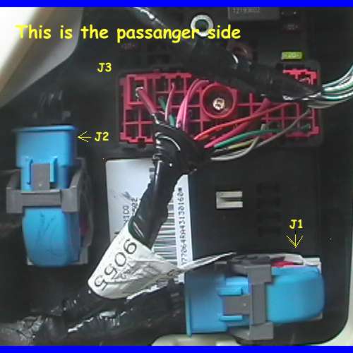
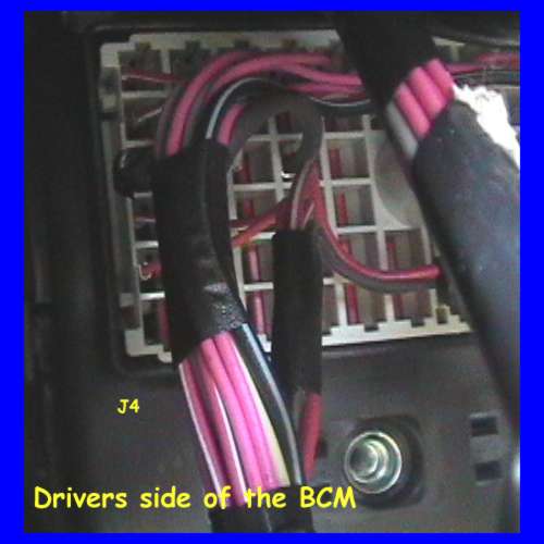
C4 is the one on the back side of the BCM reached on the driver side isn't it?  Please help I am lost on this car? just please clear up?  See when you look at the BCM J1 would also be C1 right and and J1 runs horizontal and blue and grey.  J2(C2) is vertical and the connector is blue and grey.  J3 Is a big red one it also runs horizontal.  Where is the C4(J4) is it red and on the back side or is it on the passenger side?

j68rh 
Copper - Posts: 147
Copper spacespace
Joined: March 31, 2005
Location: United States
Posted: July 07, 2005 at 7:54 AM / IP Logged  

2005 colbalt alarm/remote start wiring - Page 3 -- posted image.

2005 colbalt alarm/remote start wiring - Page 3 -- posted image.

these pictures are of the BCM and where the connectors are

zfactor 
Member - Posts: 22
Member spacespace
Joined: June 09, 2005
Location: United States
Posted: July 08, 2005 at 12:15 AM / IP Logged  
555l works great on these i have done many of them already along with numerous ions. they are the same setup. follow directfax doc 1610 when wiring up the 555l do a search in the forums it is here. look up 1610 it will come up.
Page of 3

Sorry, you can NOT post a reply.
This topic is closed.

  Printable version Printable version Post ReplyPost New Topic
You cannot post new topics in this forum
You cannot reply to topics in this forum
You cannot delete your posts in this forum
You cannot edit your posts in this forum
You cannot create polls in this forum
You cannot vote in polls in this forum

  •  
Search the12volt.com
Follow the12volt.com Follow the12volt.com on Facebook
Monday, May 6, 2024 • Copyright © 1999-2024 the12volt.com, All Rights Reserved Privacy Policy & Use of Cookies
Disclaimer: *All information on this site ( the12volt.com ) is provided "as is" without any warranty of any kind, either expressed or implied, including but not limited to fitness for a particular use. Any user assumes the entire risk as to the accuracy and use of this information. Please verify all wire colors and diagrams before applying any information.

Secured by Sectigo
the12volt.com spacer
Support the12volt.com
Top
the12volt.com spacer