the12volt.com spacer
icon

Door locks, trunk pop, remote start probs.


Post ReplyPost New Topic
< Prev Topic Next Topic >
wlg83 
Copper - Posts: 60
Copper spacespace
Joined: June 20, 2002
Location: United States
Posted: December 07, 2002 at 8:01 PM / IP Logged  
Ok. I am installing an alarm and a remote start on a 2002 Chrystler Sebring convertible. I already have all of the info on the car from a post in the vehicle info database( https://www.the12volt.com/installbay/display_topic_threads.asp?ForumID=7&TopicID=5751&PagePosition=1#thread ). Things didn't go as planned. I wired everything up as directed. BTW, the alarm is a DesignTech First Defense Deluxe(29646), with the remote that can control 4 separate vehicles. The remote start is an Audiovox add on, not sure of the model #.
As for the alarm, I programmed the remotes and started checking everything out. I have no trouble with entry points triggering the alarm(pass/driver doors, trunk and hood) and the built in shock sensor is working just fine. The parking lights work fine, as well. However, the remote start is not being activated, though I tested it and the aux output that triggers it is fine. The Power locks aren't doing anything at all, and neither is the trunk pop. I have narrowed my troubles with all of these things to be the relays, but I haven't a clue what went wrong.
One idea I came up with for the trunk... The dash button for popping the trunk is a simple push-on switch with tow wires going to it. Couldn't I just tap into one of these wires for the trunk pop? I wired it as the left relay in the diagram linked above with no luck.
The locks... Once again I wired this as the diagrams showed. Since the alarm has built-in lock relays, could I just set the polarity to + and put the resistors inline to the locks?
I still don't know what I did wrong with the relay that goes between the AUX output and the remote start module. The output from alarm is - and so is the input. Link to relay? I will look for it as soon as I post this.
It seems I just don't have a good grasp on relays yet. Thanks in advance
Beginner.
10nesne1 
Silver - Posts: 284
Silver spacespace
Joined: June 19, 2002
Location: British Columbia, Canada
Posted: December 07, 2002 at 8:20 PM / IP Logged  

Chrysler

Sebring Convertible

2001-2002

Remote Starter  Wiring Colors and Notes

Function


Vehicle  Color

Location

Start:


YELLOW

IGNITION SWITCH HARNESS *

Ignition  #1:


BLUE

IGNITION SWITCH HARNESS

Ignition #2:


GREEN/ RED (SMALL)

IGNITION SWITCH HARNESS

Ignition  #3:


N/A

Accessory:


BLACK/ ORANGE & BLACK/ WHITE

IGNITION SWITCH HARNESS

Brake  Light:


WHITE/ TAN (+)

AT SWITCH ABOVE BRAKE PEDAL

Tach  Signal:


ANY WIRE AT COIL OR INJECTOR

THAT IS NOT GREEN OR LT. GREEN

Parking Lights:


BLACK / YELLOW (+)

AT HEADLIGHT SWITCH

Headlights:


PURPLE / WHITE (+)

AT HEADLIGHT SWITCH

OEM Alarm  Disarm:


LT. GREEN/ ORANGE

IN A 26 PIN CONNECTOR AT BCM ***

OEM Alarm  Arm:


LT. GREEN/ ORANGE

IN A 26 PIN CONNECTOR AT BCM ***

Diesel  Glow Plug:


N/A

Clutch  Bypass Wire:


N/A

Notes:

 * This Vehicle Is Equipped Wiith Chrysler's Smart Key Engine Immobilizer. See Installation Note #144 - Bypassing Transponder Passive Theft System Diagram.

Chrysler

Sebring Convertible

2001-2002

Alarm and Keyless  Entry Wiring Colors and Notes

Function


Vehicle  Color

Location

Constant  +12 Volts:


PINK/BLACK

IGNITION SWITCH HARNESS

Starter  Kill:


YELLOW

IGNITION SWITCH HARNESS *

Ignition  +12 Volts:


BLUE

IGNITION SWITCH HARNESS

Dome  Lights/Superv:


TAN & TAN/RED (-)

IN A 26 PIN CONNECTOR AT BCM **

OEM Horn:


BLACK/ RED (-)

STEERING COLUMN HARNESS

Power  Lock:


WHITE/ GREEN

IN A 26 PIN CONNECTOR AT BCM ****

Power  Unlock:


WHITE/ GREEN

IN A 26 PIN CONNECTOR AT BCM ****

Trunk  Release:


BLACK/ WHITE (5-WIRE)

IN A 26 PIN CONNECTOR AT BCM *****

Alarm  Input Wire:


TAN & TAN/RED (-)

IN A 26 PIN CONNECTOR AT BCM **

Notes:

****This Wire Rests At Ground. See Installation Note #232 - Connecting For Trunk Release Diagram.
10nesne1 
Silver - Posts: 284
Silver spacespace
Joined: June 19, 2002
Location: British Columbia, Canada
Posted: December 07, 2002 at 8:24 PM / IP Logged  
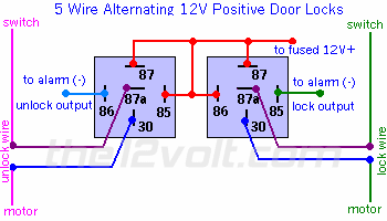
Door locks, trunk pop, remote start probs. -- posted image.
bluescreen1 
Member - Posts: 15
Member spacespace
Joined: November 28, 2002
Location: United States
Posted: December 07, 2002 at 9:32 PM / IP Logged  
if your alarm's output is negative and your car start input requires a negative then you do not need a relay in between the two.
Ruben
Innovative Sounds
Phila., Pa.
securinu 
Silver - Posts: 772
Silver spaceThis member has made a donation to the12volt.com. Click here for more info.spacespace
Joined: September 15, 2002
Location: United States
Posted: December 07, 2002 at 11:31 PM / IP Logged  
you should always use relays on resistance locks otherwise you wont get the true resistance value from a 500 ma output
Chris Luongo 
Platinum - Posts: 3,746
Platinum spaceThis member consistently provides reliable informationspace
Joined: May 21, 2002
Location: Massachusetts, United States
Posted: December 08, 2002 at 2:44 PM / IP Logged  

No relay is needed from the auxillary output of your Designtech to the input to the Audiovox.....Audiovox should be blue with black if it's the model I'm thinking of..... is it an AS-9075?

The trunk release pushbutton on the dash is a simple negative trigger, and no relay would be required.  Unfortunately, the switch is disabled when you turn the ignition off, so you'll need to 5-wire the BLACK/ white exiting the BCM.

Since you said your alarm has built-in lock relays, yes, of course you can take advantage of them.  As you said, attach the input to fused, constant positive.  Attach the appropriate resistors to the unit's lock and unlock outputs, and attach those to the white green at the BCM.

But if you want us to help you figure out the problem, we're going to need more information......have you tested the wires in the car to make sure they're the correct ones?  (I sure hope so!)  What (if anything) happens when you try to operate the intended functions?  Tell us how your relays are set up.

Also, installing two separate units (alarm and remote start) into one car is an unneccessary pain for a professional, and potentially an install nightmare for a novice----just be prepared to spend some extra time getting the two to work together properly.

wlg83 
Copper - Posts: 60
Copper spacespace
Joined: June 20, 2002
Location: United States
Posted: December 16, 2002 at 11:52 PM / IP Logged  
OK. Still have not been able to toy with the car since my original attempt. I must have forgotten to check the E-Mail notify, this whole time I thought no-one had helped, very strange for this site, you guys are awesome. The remote start is an Auto Security Audiovox AS-9151N, packaged with an RF antenna extender(AS-9166), unused.
To engage the door lock relays, should I wire the Alarm's lock outputs to be negative or positive pulse? I assume negative, just as in the Ford Probe diagram. Doing it that way will result in a positive output from the relay to the lock wire?
As for the trunk. I should wire the relay as follows?:
87  -Fused 12V(+)
87a-BCM side of cut Trunk wire
86  -Fused 12V(+)
85  -To alarm negative trunk pop (-) output
30  -Opposite BCM side of cut Trunk wire
Two unrelated questions. Does DesignTech have a good track record? I have had(despite my own problems due to lack of experience) good luck with installs so far. And where did the relay pic posted by 10nesne1 come from? Is this sort of thing included in OMEGA CD V2.0 "the disc"? Was considering purchasing one.
As always, thanks for helping this 19 year old novice.
Velocity Motors 
Moderator - Posts: 12,488
Moderator spaceThis member has made a donation to the12volt.com. Click here for more info.spaceThis member has been recognized as an authority in Electrical Theory. Click here for more info.spaceThis member has been recognized as an authority in Fabrication. Click here for more info.spaceThis member has been recognized as an authority in Mobile Audio and Video. Click here for more info.spaceThis member has been recognized as an authority in Mobile Security and Convenience. Click here for more info.spacespace
Joined: March 08, 2002
Location: Manitoba, Canada
Posted: December 17, 2002 at 12:29 AM / IP Logged  

If you wire up the door lock relays like the one posted by 10nesne1 on  December 07, 2002 at 9:24 PM   then you will need the pulse to be a (-) trigger. As far as the trunk release, you need to hook up a relay like one of the two on this diagram:

Door locks, trunk pop, remote start probs. -- posted image.

As far as DesignTech is concerned , I have heard mixed reviews with them ( but what company doesn't ). The relay diagram from above id from the Bulldog Security site. The Oemga CD will have something like this but not exactly.

Jeff
Velocity Custom Home Theater
Mobile Audio/Video Specialist
Morden, Manitoba CANADA
wlg83 
Copper - Posts: 60
Copper spacespace
Joined: June 20, 2002
Location: United States
Posted: December 17, 2002 at 12:35 AM / IP Logged  
Concerning the switch/motor sides of the cut wire for the trunk release.... the "Switch" side would be that on the BCM side(assuming I take the wire coming downward from it).
Velocity Motors 
Moderator - Posts: 12,488
Moderator spaceThis member has made a donation to the12volt.com. Click here for more info.spaceThis member has been recognized as an authority in Electrical Theory. Click here for more info.spaceThis member has been recognized as an authority in Fabrication. Click here for more info.spaceThis member has been recognized as an authority in Mobile Audio and Video. Click here for more info.spaceThis member has been recognized as an authority in Mobile Security and Convenience. Click here for more info.spacespace
Joined: March 08, 2002
Location: Manitoba, Canada
Posted: December 17, 2002 at 1:33 AM / IP Logged  
Yes that would be correct.
Jeff
Velocity Custom Home Theater
Mobile Audio/Video Specialist
Morden, Manitoba CANADA
Page of 2

  Printable version Printable version Post ReplyPost New Topic
You cannot post new topics in this forum
You cannot reply to topics in this forum
You cannot delete your posts in this forum
You cannot edit your posts in this forum
You cannot create polls in this forum
You cannot vote in polls in this forum

  •  
Search the12volt.com
Follow the12volt.com Follow the12volt.com on Facebook
Monday, May 6, 2024 • Copyright © 1999-2024 the12volt.com, All Rights Reserved Privacy Policy & Use of Cookies
Disclaimer: *All information on this site ( the12volt.com ) is provided "as is" without any warranty of any kind, either expressed or implied, including but not limited to fitness for a particular use. Any user assumes the entire risk as to the accuracy and use of this information. Please verify all wire colors and diagrams before applying any information.

Secured by Sectigo
the12volt.com spacer
Support the12volt.com
Top
the12volt.com spacer