the12volt.com spacer
icon

2000 Chevy Venture Remote Starter


Post ReplyPost New Topic
< Prev Topic Next Topic >
campuschill 
Member - Posts: 13
Member spacespace
Joined: October 25, 2005
Location: United States
Posted: November 04, 2005 at 12:06 PM / IP Logged  
Thanks for answering my questions.
Today i started the installation of code alarm of the CSI 400 remote starter. I am in the step of connecting the wire to the tachometer in the Engine compartment, but am unable to locate it. Can somebody help me in locating it.
Also what is a firewall connector and where is it located.
This is the first time am working on this van and doing a self intallation of a RS, so i will appreciate any help. Thanks again.
campuschill 
Member - Posts: 13
Member spacespace
Joined: October 25, 2005
Location: United States
Posted: November 04, 2005 at 1:45 PM / IP Logged  
I found a white wire in the harness as mentioned in the wiring diagram section.
In the code alarm instruction manual to verify that it is the correct wire, it is asked to connect a multimeter to measure AC volts between a constant 12VDC (+ve terminal of multimeter) source and the -Ve terminal of multimeter to tacho wire. The manual says the voltage will increase when the engine is running and the gas pedal is pressed.
I tried the above test, as soon i start the engine the voltage is 1.5 V AC and when i press the gas it goes upto 2.5 V AC or sometimes 3 V AC. If further press the gas pedal it constants about 2 V AC. Is this the right wire..please guide me. Thanks
kgerry 
Platinum - Posts: 3,455
Platinum spaceThis member consistently provides reliable informationspace
Joined: February 07, 2004
Location: Saskatchewan, Canada
Posted: November 04, 2005 at 2:00 PM / IP Logged  
sounds like it is
Kevin Gerry
Certified Electronics Technician
MECP First Class Installer
Owner/Installer
Classic Car Audio
since 1979
campuschill 
Member - Posts: 13
Member spacespace
Joined: October 25, 2005
Location: United States
Posted: November 04, 2005 at 6:31 PM / IP Logged  
Thanks Kevin,
However i could not get the system working. The CSI-400 has capability of both RS and also keyless entry, but i wanted only the RS, since i have OEM keyless entry in the minivan. To achieve this, following are the wires i connected
(A)
1) I connected the 6-pin power harness to the wires in the harness at the ignition switch.
(B)Twelve Pin harness is connected as follows
1) wire to the Tachometer, as acknowledged by Kevin
2) wire to ground
3) wire to control safety switch
4) wire to positive shutdown brake switch
(C)
1) Program switch was connected to the module
(D)
1) Antenna was connected to the module
Wires I ignored
1) Auxillary output wires
2) Door lock output wires
3) Ignition bypass to exisiting aftermarket alarm
4) Channel 3 low current negative output to operate electric trunk release
5) Active output (300 ma Max)
6) Parking Brake input
7) Parking light source
8) To vehicle parking light
9) Low current defroster activation output
10) Negative shutdown wire (hood pin switch)
11) Diesel glow plug
At this condition, when i try to start the van with the key, it does not start, so i did not even try remote starting. As soon i disconnect the 12 point harness from the RS module (the 6 pin power harness is still connected) and try the key, engine starts and everything works normal.
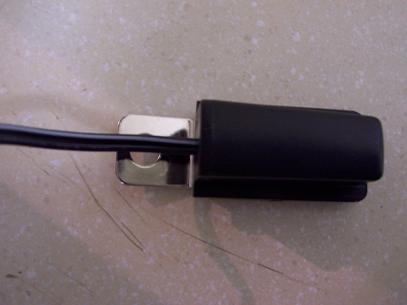
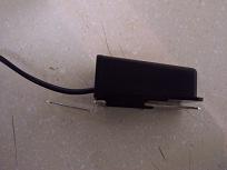
Further i am attaching the image of the hood pin switch, i donot understand how it works, hence dont know how and where to place it under the hood. Also, the manual specifies the connection for one of the wires of the hood pin switch to the 12 pin harness, however does not say whether the other one has to goto ground or positive supply.
Need help and advice
2000 Chevy Venture Remote Starter - Page 2 -- posted image.2000 Chevy Venture Remote Starter - Page 2 -- posted image.
mo12v 
Platinum - Nominee - Posts: 2,748
Platinum - Nominee spaceThis member consistently provides reliable informationspace
Joined: September 30, 2003
Location: Afghanistan
Posted: November 04, 2005 at 6:53 PM / IP Logged  

12 PIN Harness:

Where do you have # 3 & 4 connected??  What wires & Color on Vehicle?

MO
Don't Learn from Others Mistakes
You Might Be the One That Knows.
campuschill 
Member - Posts: 13
Member spacespace
Joined: October 25, 2005
Location: United States
Posted: November 04, 2005 at 7:27 PM / IP Logged  
Thanks MO
I connected #3 to one of the wires of the control switch, the other wire of the switch went to ground.
I connected #4 to brake switch wire (color brown). This wire registered positive 12V when the brake was pressed.
mo12v 
Platinum - Nominee - Posts: 2,748
Platinum - Nominee spaceThis member consistently provides reliable informationspace
Joined: September 30, 2003
Location: Afghanistan
Posted: November 04, 2005 at 7:38 PM / IP Logged  
If you were to connect R/S ...........& Unhook TACH wire from R/S....will your Vehicle START with the Key?
MO
Don't Learn from Others Mistakes
You Might Be the One That Knows.
campuschill 
Member - Posts: 13
Member spacespace
Joined: October 25, 2005
Location: United States
Posted: November 05, 2005 at 9:37 AM / IP Logged  
I think i had a problem with ground, the van starts with the key with the same wiring as above. However no luck with the remote starter.
Do i have to connect the remaining wires, like the hood pin switch. The manual says hood pin is a negative shutdown, so leaving this un-connected should not make a difference i thought. I donot have any idea about the other wires that are left un-connected.
When i press the remote start switch, i see relay ticking noise in the module.
Please advice
campuschill 
Member - Posts: 13
Member spacespace
Joined: October 25, 2005
Location: United States
Posted: November 06, 2005 at 10:23 AM / IP Logged  
Where is the firewall connector located in a 2000 Chevy venture. I was looking for the parking lights source with brown color wire, which i was unable to locate.
I did not hook up the BYPASS module DEI555G, so i tried the remote start with the key in the ignition, no luck yet.
Please do advice on placing the hood pin trigger, based on the image above. When i press there is continuity between the wires in the hood pin switch and open when not pressed. So it looks like the switch will connect to ground when the hood is closed, is this a right setting.
Thanks for your continued response
campuschill 
Member - Posts: 13
Member spacespace
Joined: October 25, 2005
Location: United States
Posted: November 07, 2005 at 8:36 PM / IP Logged  
Can somebody help?
Page of 3

  Printable version Printable version Post ReplyPost New Topic
You cannot post new topics in this forum
You cannot reply to topics in this forum
You cannot delete your posts in this forum
You cannot edit your posts in this forum
You cannot create polls in this forum
You cannot vote in polls in this forum

  •  
Search the12volt.com
Follow the12volt.com Follow the12volt.com on Facebook
Saturday, May 4, 2024 • Copyright © 1999-2024 the12volt.com, All Rights Reserved Privacy Policy & Use of Cookies
Disclaimer: *All information on this site ( the12volt.com ) is provided "as is" without any warranty of any kind, either expressed or implied, including but not limited to fitness for a particular use. Any user assumes the entire risk as to the accuracy and use of this information. Please verify all wire colors and diagrams before applying any information.

Secured by Sectigo
the12volt.com spacer
Support the12volt.com
Top
the12volt.com spacer