the12volt.com spacer
icon

Delayed relay output?


Post ReplyPost New Topic
< Prev Topic Next Topic >
dualsport 
Silver - Posts: 983
Silver spacespace
Joined: September 27, 2005
Location: United States
Posted: November 04, 2005 at 8:36 PM / IP Logged  
Take a look at this Post again
and see if you can use that to provide your timed output. The circuit he drew out is for a short pulse output, but you should be able to use it too-
You just need to use a larger cap and resistor to stretch out the 'on' time to 10 minutes.
icarus_icarus 
Copper - Posts: 229
Copper spacespace
Joined: November 01, 2005
Location: Ontario, Canada
Posted: November 04, 2005 at 9:00 PM / IP Logged  

Delayed relay output? - Page 2 -- posted image.

The part that says 'Switch and Time Delay' in the diagram is internal on the switch.

I don't know enough to figure out exactly what to do with your description in the other guys post dualsport, sorry... I have no idea what size cap or resistor to use etc...

dualsport 
Silver - Posts: 983
Silver spacespace
Joined: September 27, 2005
Location: United States
Posted: November 04, 2005 at 9:43 PM / IP Logged  
To get about 10 minutes, you can try a cap value of 100uF and a resistor of 5.6Mohms, then if you wire it up as shown in the other post, you can connect the relay across the wires on the right side of the defrost switch relay assembly. To be safe, you should probably cut the BR/LB wire at the bottom and use the NC to COM (with the COM going to the defrost grid side, and the NC to the OEM defrost relay side) contacts of your added relay to reconnect it when you're not controlling it remotely. Then when you power up your added relay, the grid will get power from the NO contact, which is connected to the top BK/Y wire.
If someone can confirm that it won't bother the OEM defrost relay to have 12V applied directly to the grid, then you don't need to bother with the NC connection scheme. My guess is that it'd probably be okay, but better to be safe and not risk damaging the OEM relay timer circuit.
icarus_icarus 
Copper - Posts: 229
Copper spacespace
Joined: November 01, 2005
Location: Ontario, Canada
Posted: November 04, 2005 at 10:51 PM / IP Logged  

Cool, thanks, I think that makes sense now! :)

Will 1/4 watt 5% resistors, and aluminum electrolytic caps work for this? (typical resistors and caps found at Radio Shack etc)

I don't know of any places around here other than Radio Shack (theSource up here now) that sell stuff like this, I'll have to look around to see where I can get the transistor from :(

So theres no way I can do this with just relays/caps/diodes similar to the original picture?

icarus_icarus 
Copper - Posts: 229
Copper spacespace
Joined: November 01, 2005
Location: Ontario, Canada
Posted: November 04, 2005 at 11:27 PM / IP Logged  

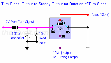
dualsport, what about something a 'lil simpler like this:

Delayed relay output? - Page 2 -- posted image.

My understanding of this circuit was a single pulse will energize the relay according to what size cap and resistor you use... If I used the cap and resistor values you mentioned, would a single pulse from the RS keep this energized for time I want?

icarus_icarus 
Copper - Posts: 229
Copper spacespace
Joined: November 01, 2005
Location: Ontario, Canada
Posted: November 04, 2005 at 11:32 PM / IP Logged  

ps: Maybe to clarify my inquiry (or confuse me more about the above diagram!):

I know I wouldn't have a constantly pulsing input to the 86 terminal of the relay, but all that does is reset (recharge) the cap so its on constantly, hence it would stay on after the last pulse (or just the one pulse as in my case) for the time determined by the cap and resistor?!...

I hope I'm not reading into this more than I need to as I know I am bad for this at times!

icarus_icarus 
Copper - Posts: 229
Copper spacespace
Joined: November 01, 2005
Location: Ontario, Canada
Posted: November 04, 2005 at 11:34 PM / IP Logged  

oh, and terminal 30 of the relay would goto the BR/LB wire of my car diagram...!?

dualsport 
Silver - Posts: 983
Silver spacespace
Joined: September 27, 2005
Location: United States
Posted: November 05, 2005 at 8:18 AM / IP Logged  
That circuit wouldn't work for the timing period you're looking for; you need to put the transistor in place to drive the relay. The relay coil draws a relatively large current, and what would happen is that it would discharge your cap almost immediately once the trigger signal turned back off. You'd need an enormous cap, which your drive signal probably wouldn't even be able to charge up in time.
With the transistor, it's basically voltage driven, and draws essentially no current during the 'on' period. Then, once your trigger signal turns off, the cap can only discharge through the resistor, since the only other paths would be the reverse biased diode and the transistor, which like open circuits.
The circuit just extends the on period from when you turn off your trigger signal; if you put in a constant on (+) signal, the relay would stay on for as long as it's high.
Yes, term 30 should be the COM contact of your relay, and should go to the BR/LB defroster grid wire side.
Just occurred to me you might be using a (-) signal from the alarm; not a (+) pulsed signal; if that's the case, it would have to be inverted first to get a signal that goes to +V when you push the remote control.
Your diagram shows the power input to the defrost relay to be constant 12V; connect the (+) of your relay coil to source that only goes on when the car is remote started, so it can't come on at any other time.
You can check online at Mouser.com for the parts, they don't have a minimum order, so you'd just need to spring for the shipping charges. May as well get a bunch of stuff with assorted values if you do order.
icarus_icarus 
Copper - Posts: 229
Copper spacespace
Joined: November 01, 2005
Location: Ontario, Canada
Posted: November 05, 2005 at 1:49 PM / IP Logged  

I didn't realize this about the current across the relay coil, I'm learning though!

I checked out Mouser, but they list hundreds of different things for resistors/caps/etc... I'lll have to look around when I have some more time to sit down and check out thier site...

I do have a (-) signal from the RS, so figured I had to invert it as well.

Is there any kind of formula or way of figuring out what different size caps and resistors will do to the timing of the circuit so when I do order stuff I can tweak it a bit if need be?

Thanks for the great info you have been posting dualsport, it's nice to see someone willing to help so much!

Jon

kgerry 
Platinum - Posts: 3,455
Platinum spaceThis member consistently provides reliable informationspace
Joined: February 07, 2004
Location: Saskatchewan, Canada
Posted: November 05, 2005 at 4:27 PM / IP Logged  
or you could just use the DEI 611T which will do exactly what you want.... it's a timed latching relay module
Kevin Gerry
Certified Electronics Technician
MECP First Class Installer
Owner/Installer
Classic Car Audio
since 1979
Page of 11

  Printable version Printable version Post ReplyPost New Topic
You cannot post new topics in this forum
You cannot reply to topics in this forum
You cannot delete your posts in this forum
You cannot edit your posts in this forum
You cannot create polls in this forum
You cannot vote in polls in this forum

  •  
Search the12volt.com
Follow the12volt.com Follow the12volt.com on Facebook
Friday, March 29, 2024 • Copyright © 1999-2024 the12volt.com, All Rights Reserved Privacy Policy & Use of Cookies
Disclaimer: *All information on this site ( the12volt.com ) is provided "as is" without any warranty of any kind, either expressed or implied, including but not limited to fitness for a particular use. Any user assumes the entire risk as to the accuracy and use of this information. Please verify all wire colors and diagrams before applying any information.

Secured by Sectigo
the12volt.com spacer
Support the12volt.com
Top
the12volt.com spacer