the12volt.com spacer
icon

Delayed relay output?


Post ReplyPost New Topic
< Prev Topic Next Topic >
icarus_icarus 
Copper - Posts: 229
Copper spacespace
Joined: November 01, 2005
Location: Ontario, Canada
Posted: November 07, 2005 at 5:45 PM / IP Logged  

I have many spools of 14ga automotive wire (or is it 16ga?!) and some 10ga I will use for the defrost line (the factory line is 12-10ga for the defrost) ...soldering the diode to this should be fun ;)

I used to have a program similar to Orcad where you can design and 'test' circuits, I'll have to dig it out and see what one it is if I can even find it now! I did find my box full of resistors, caps, and other goodies though :)

icarus_icarus 
Copper - Posts: 229
Copper spacespace
Joined: November 01, 2005
Location: Ontario, Canada
Posted: November 09, 2005 at 2:16 AM / IP Logged  

I hope you guys don't shoot me for this, but guess what I got apart??? Delayed relay output? - Page 5 -- posted image.

The blue arrow is what the toggle switch presses against to turn the defrost on/off...

The red arrow is a middle connection on the metal bar running around the coil (there is three connections to the board on the barDelayed relay output? - Page 5 -- posted image....

The green arrows are the real fine wires going to the coil itself...

Delayed relay output? - Page 5 -- posted image.

Now should I ask is there a way to use a relay to activate it using the factory timer etc?

I can scan the backside or do an overlay of what wires go where from the other wiring diagram if need be...

Thanks,

Jon

ps: the starter is in totally now, just need to hook up the power wires and this defrost idea if it happens :) I'd still be pondering all this if it wasn't for you guys though!

icarus_icarus 
Copper - Posts: 229
Copper spacespace
Joined: November 01, 2005
Location: Ontario, Canada
Posted: November 09, 2005 at 2:18 AM / IP Logged  

Well, it will happen, either the way you have already done for me or if I can do something with this now Delayed relay output? - Page 5 -- posted image.

danijels 
Member - Posts: 4
Member spacespace
Joined: November 09, 2005
Location: Slovenia
Posted: November 09, 2005 at 4:49 AM / IP Logged  
icarus_icarus wrote:

Delayed relay output? - Page 5 -- posted image.

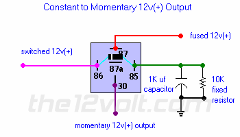
Can anyone tell me detailed specification of relay capacitator, resistor, diode, .... 

Danny
dualsport 
Silver - Posts: 983
Silver spacespace
Joined: September 27, 2005
Location: United States
Posted: November 09, 2005 at 9:09 AM / IP Logged  
Your defroster pushbutton actually moves the contact arm of the relay? I guess it will latch in when that's done, and a timer circuit controls the coil power after that.
If that's in fact what it does, then try to connect terms 30 and 87 of your aftermarket relay to the two contact nodes on that board relay, probably soldering wires on from the back side of the board.
That would simulate the operation of pushing the button.
*Actually, you should check if that would work, because it's possible that the relay won't pull in enough to close by just providing the electrical contact, without mechanically closing the OEM relay contacts. The hold current is much less than the pull in current, so it could have been designed to just have enough power to hold it closed, but not enough to pull it closed from an open position. If you can, just take a jumper and connect those two points while it's connected to the car, and see if the relay will pull in. If you have to manually push the contact arm closed before it'll latch, then you'll have to go to plan A.
If it does close with the electrical-only connection, you also might check that the power to the defroster circuit is actually enabled when you hit the remote control button, some remote start setups power up the ignition separately first, and acc/defroster power a short time later. If everything comes on at once with yours, then you should be set. Just a matter of running the wires out from your OEM timer switch.
icarus_icarus 
Copper - Posts: 229
Copper spacespace
Joined: November 01, 2005
Location: Ontario, Canada
Posted: November 09, 2005 at 3:35 PM / IP Logged  

Yah, it acutally pushes it closed, turning it off breaks the connection... I was going to try to see if I could get it to activate like you mentioned with the switch plugged into the car... but its pouring rain with hail off and on, so I'm staying dry ;)

The back side does have many points to solder to, so finding a spot to solder too won't be hard, this remins me of lil circuits and stuff I used to play 'round with at school years ago :)

Delayed relay output? - Page 5 -- posted image.

If the rain stops, I'll go out and check to see what happens, I need a garage my car will fit into!!! lol :)

dualsport 
Silver - Posts: 983
Silver spacespace
Joined: September 27, 2005
Location: United States
Posted: November 09, 2005 at 6:51 PM / IP Logged  
I'm in the same boat, if it's raining out, I'm not doing anything either.
Can you see what IC they have on there? Is it a 555 timer or something?
Seems to be three other components underneath the relay too. That defrost timer could be useful for other things like turbo timers too, might be handy to draw it out and see how it works.
icarus_icarus 
Copper - Posts: 229
Copper spacespace
Joined: November 01, 2005
Location: Ontario, Canada
Posted: November 10, 2005 at 8:13 PM / IP Logged  

The IC says '63160-39     L8539' and has a Motorola symbol on it. I checked quick online and couldn't find anything about it?! There is two 1Kohm resistors and I think a diode (all I can read on it is 1N... & it looks to have a stripe on the one end) under the relay as well as another 2.5Mohm resistor that you can see in the pic, the black cap is 4.7u 16V and the yellow (cap?) says '.1/5/100 Intercap' on it... I am trying to get a schematic done of it...

Will it hurt you think to put 12V across those fine relay wires (green arrows in upper pic.) or should I solder somewhere else on the backside? I also need to resolder that yellow lamp to the board again as it looks like it is coming loose at the pins...

fingaz22 
Silver - Posts: 410
Silver spaceThis member has made a donation to the12volt.com. Click here for more info.spacespace
Joined: March 11, 2005
Location: United States
Posted: November 10, 2005 at 8:40 PM / IP Logged  
use a relay to make the contact. instead of the button pushing on the arm of the relay in the timer curcuit the external relay will make the contact use 87 and 30 to get a closed loop on the factory one. by the looks of it its the second big solder joint in from the top left in the second picture. and the big solder joint on the bottom above the yellow lamp.
JUST ONE MORE AMP!!!
hu,alpine cva 1005/dva 5205
sound processor,symmetry(first one).
sub amp,power 1000 the terminator.(1992).
subs,spl comp dual 1 ohms.
punch 150hd on a 10" ev.
alotofhighs
dualsport 
Silver - Posts: 983
Silver spacespace
Joined: September 27, 2005
Location: United States
Posted: November 10, 2005 at 9:55 PM / IP Logged  
Yeah, solder your relay connections to the back, it'd be easier than trying to go directly to the coil wires. They're very delicate to work with, and you don't definitely don't want to damage it in the process.
If you can confirm the relay latches in with the 12V applied to the coil connections, you can control it by applying the 12V from your external relay to the coil. Then you can get away with using a smaller relay, since all it needs to do then is supply relay coil power.
If you go directly to the contacts, you'd need a heavier duty relay, since it'd be momentarily driving the defroster grid until the OEM relay latches in.
Be *very* careful which side of the coil you connect to if you do go to the coil; if you apply 12V to the wrong side, it'd probably blow the timer circuit, which I think works by grounding the low side of the coil. After the designated time period, it opens up the ground, and the relay should unlatch. My guess anyway.
You can check to see if that's how it works by measuring the voltage on the relay coil before and after you latch it on; don't connect to the low voltage side-
When testing this out, you could try using a current limiting resistor that you connect to 12V, and the other side to the side of the coil you think will latch it in; maybe 200 ohms. If you have the wrong side, that should protect the timer driver.
If your relay can handle the defroster current without problem, it would be a safer bet to just connect to the same points as the OEM relay. Then you don't have to figure out which is which.
My guess is that the relay coil trace going to the mystery chip is the one to stay away from; so you can measure the voltage on the other side when you push the defroster button and see if it goes to 12v and stays there. If it does, that's the one you want.
Page of 11

  Printable version Printable version Post ReplyPost New Topic
You cannot post new topics in this forum
You cannot reply to topics in this forum
You cannot delete your posts in this forum
You cannot edit your posts in this forum
You cannot create polls in this forum
You cannot vote in polls in this forum

  •  
Search the12volt.com
Follow the12volt.com Follow the12volt.com on Facebook
Friday, November 8, 2024 • Copyright © 1999-2024 the12volt.com, All Rights Reserved Privacy Policy & Use of Cookies
Disclaimer: *All information on this site ( the12volt.com ) is provided "as is" without any warranty of any kind, either expressed or implied, including but not limited to fitness for a particular use. Any user assumes the entire risk as to the accuracy and use of this information. Please verify all wire colors and diagrams before applying any information.

Secured by Sectigo
the12volt.com spacer
Support the12volt.com
Top
the12volt.com spacer