the12volt.com spacer
icon

Delayed relay output?


Post ReplyPost New Topic
< Prev Topic Next Topic >
icarus_icarus 
Copper - Posts: 229
Copper spacespace
Joined: November 01, 2005
Location: Ontario, Canada
Posted: November 06, 2005 at 8:40 PM / IP Logged  

The second relay has 3 terminals going to ground (87,30,85)?

I already have two circuits running off the acc wire, so could I wire it with a constant 12V and have the ground goto the 'ground out while running' wire on the RS? Would this do what I want?

Delayed relay output? - Page 4 -- posted image.

dualsport 
Silver - Posts: 983
Silver spacespace
Joined: September 27, 2005
Location: United States
Posted: November 06, 2005 at 10:06 PM / IP Logged  
Well, if you use a constant source like that, it's not going to be timed, and will stay on all the time once you turn it on (!).
It'd be better to use the 12V source that's only active during the remote start (the wire from the remote start that feeds the accessory) just as he drew in the original diagram, because it has to be able to turn off to shut the relays off again.
You don't really need to use the ground out while running for term 30 on the second relay, though that would work fine also. If it's any easier, just connect to any constant ground you can get to. Term 85 on the second relay is just the trigger input to turn on the relay, not a constant ground.
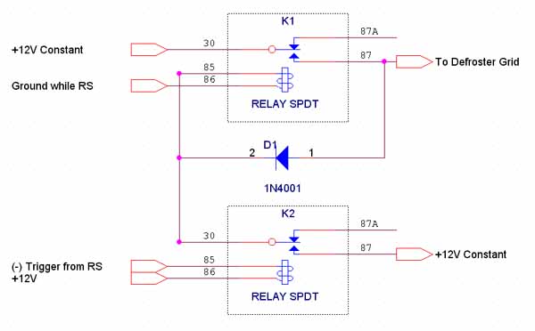
The added diode lets you remove the trigger input and keep that second relay latched, because when the relay closes, term 87 gets connected to ground, and then holds the trigger term 85 at ground (through the diode) as long as term 86 stays at 12V.
That's why you need to be able to remove the 12V to the second relay when the remote start period is over, in order to shut the relay back down.
If your remote start period is longer than you want to leave the defroster on for, you'd have to shut the remote start off manually to turn off the defroster, then restart. If it's only few minutes more, it should be no problem to run the defroster longer.
dualsport 
Silver - Posts: 983
Silver spacespace
Joined: September 27, 2005
Location: United States
Posted: November 06, 2005 at 10:30 PM / IP Logged  
As KPierson said, the part you have to be careful with is getting the isolation diode with enough current capacity to supply the full current draw of all your accessories. Not sure what the current rating on the accessory output from the alarm is, but that should probably be the minimum value to shoot for when selecting the diodes. I
An alternative is to use that "ground out while RS" signal as the relay enable line; then you don't have to get the high current diodes-
Don't have drawing capability, but here's the details:
3 components: two relays, one standard low pwr diode
Relay 1:
Term 30 to 12V Constant (high power for defroster pwr)
Term 86 to your "Ground while RS" signal
Term 87 to Defroster Grid
Term 85 to Relay 2 Term 30
Diode between Relay 1's term 87 and 85 (stripe towards 85)
Relay 2:
Term 87 to 12V Constant (low pwr)
Term 86 to 12V Constant (low pwr)
Term 85 to (-) trigger pulse from RS
That should do the trick-
dualsport 
Silver - Posts: 983
Silver spacespace
Joined: September 27, 2005
Location: United States
Posted: November 07, 2005 at 1:08 PM / IP Logged  
Got set up for schematic drawing now-
Delayed relay output? - Page 4 -- posted image.
icarus_icarus 
Copper - Posts: 229
Copper spacespace
Joined: November 01, 2005
Location: Ontario, Canada
Posted: November 07, 2005 at 3:03 PM / IP Logged  

So this will 'latch' on when I hit the aux button on the remote, and only while running under RS, for the time I have the module set for (15minutes) & I don't need to worry about the higher powered diodes/transistors etc! Sounds great to me! Delayed relay output? - Page 4 -- posted image.

I'm impressed to see a forum where everyone is willing to help out so much, you don't see this alot, esp to the extent you guys have been helping me! I hope to return the favor when I can.

Thank you. I'm going to finish this up this week if I get some time between work. I'll let ya'll know how it turns out :)

Jon

dualsport 
Silver - Posts: 983
Silver spacespace
Joined: September 27, 2005
Location: United States
Posted: November 07, 2005 at 3:53 PM / IP Logged  
It's a little like doing crossword puzzles, just for fun-
At least now I can draw the schematics out, should be handy.Delayed relay output? - Page 4 -- posted image.
Hope it works out, let us know!
icarus_icarus 
Copper - Posts: 229
Copper spacespace
Joined: November 01, 2005
Location: Ontario, Canada
Posted: November 07, 2005 at 4:08 PM / IP Logged  

What program did you end up using for the drawings?

dualsport 
Silver - Posts: 983
Silver spacespace
Joined: September 27, 2005
Location: United States
Posted: November 07, 2005 at 4:21 PM / IP Logged  
I used Orcad Capture, makes it really easy; all the components are available to just drop onto the page without needing to draw them out, like I started to do with a sketch program. That was waay too tedious, so I gave that up real quick..
icarus_icarus 
Copper - Posts: 229
Copper spacespace
Joined: November 01, 2005
Location: Ontario, Canada
Posted: November 07, 2005 at 5:00 PM / IP Logged  

On relay K2, does it matter the source for the 12V @ term 86? (ie: can it and 87 be powered by the same 12V?)

dualsport 
Silver - Posts: 983
Silver spacespace
Joined: September 27, 2005
Location: United States
Posted: November 07, 2005 at 5:16 PM / IP Logged  

They're the same, so you can just connect them together.

You can just use light gauge wire for those, because all they do is drive the relay coils; the high power one is the one feeding the defroster, so you should use wire of sufficient gauge to handle the current there.

Page of 11

  Printable version Printable version Post ReplyPost New Topic
You cannot post new topics in this forum
You cannot reply to topics in this forum
You cannot delete your posts in this forum
You cannot edit your posts in this forum
You cannot create polls in this forum
You cannot vote in polls in this forum

  •  
Search the12volt.com
Follow the12volt.com Follow the12volt.com on Facebook
Friday, March 29, 2024 • Copyright © 1999-2024 the12volt.com, All Rights Reserved Privacy Policy & Use of Cookies
Disclaimer: *All information on this site ( the12volt.com ) is provided "as is" without any warranty of any kind, either expressed or implied, including but not limited to fitness for a particular use. Any user assumes the entire risk as to the accuracy and use of this information. Please verify all wire colors and diagrams before applying any information.

Secured by Sectigo
the12volt.com spacer
Support the12volt.com
Top
the12volt.com spacer