the12volt.com spacer
icon

95 Camaro alarm/RS


Post ReplyPost New Topic
< Prev Topic Next Topic >
93whitesol 
Member - Posts: 15
Member spacespace
Joined: December 05, 2004
Location: United States
Posted: January 28, 2006 at 4:41 PM / IP Logged  
I'm trying to install a hornet 564T (DEI) remote start/alarm into my 95 camaro, and I'm having trouble connecting the door locks. The RS has 2 wires for the door locks (one is -lock/+unlock the other -unlock/+lock) These 2 wires give me a postive reading from a test light when I hit lock or unlc**k from the remote, but once I connect these to the correct wires in the car I no longer get any positive output from them when I hit the buttons on the remote. What does this mean, and what am I doing wrong? I've tried to go straight to the master switch at the passenger door, but I still get no output from the RS when those wires are connected.
mo12v 
Platinum - Nominee - Posts: 2,748
Platinum - Nominee spaceThis member consistently provides reliable informationspace
Joined: September 30, 2003
Location: Afghanistan
Posted: January 28, 2006 at 4:49 PM / IP Logged  

You will need to use Relays if your unit does not do 5 wire Reversal

Power LockLIGHT BLUE**DRIVER KICK TEST FROM
Power UnlockDARK BLUEPANEL PASSENGER SWITCH!
** If Equipped With OEM Keyless Entry: Lock- RED / BLACK, Unlock- ORANGE / BLACK At Keyless Entry Module In Passenger Kick Panel. Passenger Switch Is Primary Switch!!
Reversal Rest At Ground Door Locks

MO
Don't Learn from Others Mistakes
You Might Be the One That Knows.
mike swanson 
Copper - Posts: 290
Copper spacespace
Joined: January 28, 2003
Location: United States
Posted: January 28, 2006 at 4:50 PM / IP Logged  
Door Lock: Light Blue- Driver's Kick Panel            (Reverse Polarity) You need relays
Door Unlock Black Passenger's Switch is Master Switch
93whitesol 
Member - Posts: 15
Member spacespace
Joined: December 05, 2004
Location: United States
Posted: January 28, 2006 at 4:53 PM / IP Logged  
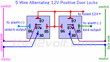
so should I be using this diagram here?
95 Camaro alarm/RS -- posted image.
mo12v 
Platinum - Nominee - Posts: 2,748
Platinum - Nominee spaceThis member consistently provides reliable informationspace
Joined: September 30, 2003
Location: Afghanistan
Posted: January 28, 2006 at 5:18 PM / IP Logged  
yes......test from pass door
MO
Don't Learn from Others Mistakes
You Might Be the One That Knows.
93whitesol 
Member - Posts: 15
Member spacespace
Joined: December 05, 2004
Location: United States
Posted: January 28, 2006 at 5:27 PM / IP Logged  
thanks for all the quick answers.....just a few more questions....This all applies even though the car had a factory keyless entry?
and is that diagram correct?
one relay has 85 to 12v 86 to alarm unlock
the other has 86 to 12v 85 to alarm lock
I've seen another diagram somewhere which shows both 85 to 12v and both 86 to the alarm
mo12v 
Platinum - Nominee - Posts: 2,748
Platinum - Nominee spaceThis member consistently provides reliable informationspace
Joined: September 30, 2003
Location: Afghanistan
Posted: January 28, 2006 at 5:42 PM / IP Logged  

93whitesol wrote:
This all applies even though the car had a factory keyless entry? and is that diagram correct?

yes to both...........

Be sure you use SPDT Realys.....( Single Pole Double Throw )

MO
Don't Learn from Others Mistakes
You Might Be the One That Knows.
93whitesol 
Member - Posts: 15
Member spacespace
Joined: December 05, 2004
Location: United States
Posted: January 28, 2006 at 6:40 PM / IP Logged  
Im still a little confused because I dont have a single wire going from the switch to the motor. I have the wires from the switch going into what I believe is a power door lock module or something like that, and there's wires coming out of there going to the motors.   So how do I hook up wires 86&30 and 85&30 (the leads going to the switch/motor)?
93whitesol 
Member - Posts: 15
Member spacespace
Joined: December 05, 2004
Location: United States
Posted: January 28, 2006 at 6:42 PM / IP Logged  
I meant to ask about 87a&30 in the above post which are the leads going to the switch/wire
mo12v 
Platinum - Nominee - Posts: 2,748
Platinum - Nominee spaceThis member consistently provides reliable informationspace
Joined: September 30, 2003
Location: Afghanistan
Posted: January 28, 2006 at 8:21 PM / IP Logged  

Do NOT Reverse wires on PIN 30 & 87a.  You can damage Switch

This is 5 wire Reversal:

2 SPDT RELAYS:

Cut LOCK  & UNLOCK Wires in Half.

One Half goes to SWITCH ( when you push Lock Switch, it will show 12 Volts....)
One Half goes to ACTUATOR

Relay 1

LOCK:

PIN 87 =  12 Volts ( + ) Constant
PIN 87a =  wire from Door Lock Switch
PIN 30 =  wire to Actuator
PIN 85 = Negative Lock Output from Alarm
PIN 86 = Constant 12 volt ( + )

Relay 2

UNLOCK:

PIN 87 =  12 Volts ( + ) Constant
PIN 87a =  wire from Door UnLock Switch
PIN 30 =  wire to Actuator
PIN 86 = Negative UnLock Output from Alarm
PIN 85 = Constant 12 volt ( + )

MO
Don't Learn from Others Mistakes
You Might Be the One That Knows.
Page of 3

  Printable version Printable version Post ReplyPost New Topic
You cannot post new topics in this forum
You cannot reply to topics in this forum
You cannot delete your posts in this forum
You cannot edit your posts in this forum
You cannot create polls in this forum
You cannot vote in polls in this forum

  •  
Search the12volt.com
Follow the12volt.com Follow the12volt.com on Facebook
Sunday, August 17, 2025 • Copyright © 1999-2025 the12volt.com, All Rights Reserved Privacy Policy & Use of Cookies
Disclaimer: *All information on this site ( the12volt.com ) is provided "as is" without any warranty of any kind, either expressed or implied, including but not limited to fitness for a particular use. Any user assumes the entire risk as to the accuracy and use of this information. Please verify all wire colors and diagrams before applying any information.

Secured by Sectigo
the12volt.com spacer
Support the12volt.com
Top
the12volt.com spacer