


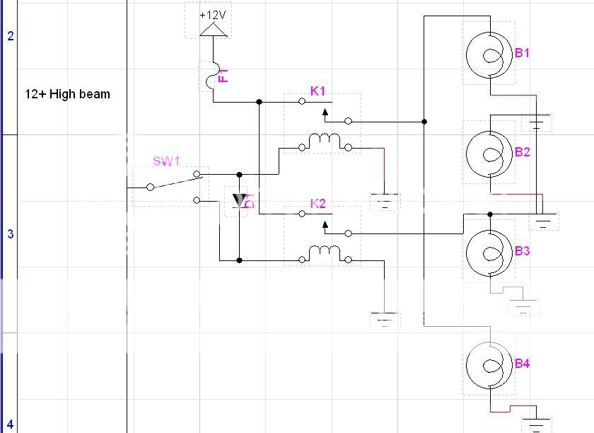
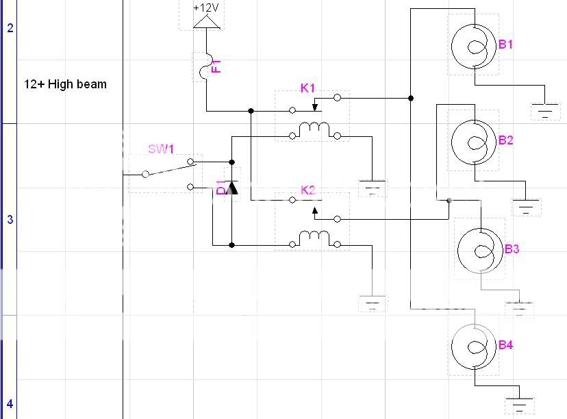
Odd request. Circuit diagram needed.
Home /
the12volt's Install Bay /
General Discussion / Odd request. Circuit diagram needed. ( Topic Closed)


Posted: April 13, 2006 at 7:49 PM / IP Logged


Posted: April 13, 2006 at 8:02 PM / IP Logged
 the12volt
 Posted: April 13, 2006 at 8:05 PM / IP Logged
Posted: April 13, 2006 at 8:11 PM / IP Logged
Posted: April 13, 2006 at 8:17 PM / IP Logged
Posted: April 13, 2006 at 8:18 PM / IP Logged
Posted: April 13, 2006 at 8:19 PM / IP Logged
Posted: April 13, 2006 at 8:28 PM / IP Logged
Posted: April 18, 2006 at 4:38 AM / IP Logged
 I just want to work back in my field but whats up with isntallers these days? How the hell did he become a manager when his knowledge is not upto scratch.
Posted: April 18, 2006 at 4:45 AM / IP Logged
Sorry, you can NOT post a reply.
This topic is closed.
 Printable version
| You cannot post new topics in this forum You cannot reply to topics in this forum You cannot delete your posts in this forum You cannot edit your posts in this forum You cannot create polls in this forum You cannot vote in polls in this forum |

| Search the12volt.com |
Follow the12volt.com 
Thursday, May 14, 2026 • Copyright © 1999-2026 the12volt.com, All Rights Reserved • Privacy Policy & Use of Cookies

Thursday, May 14, 2026 • Copyright © 1999-2026 the12volt.com, All Rights Reserved • Privacy Policy & Use of Cookies
Disclaimer:
*All information on this site ( the12volt.com ) is provided "as is" without any warranty of any kind, either expressed or implied, including but not limited to fitness for a particular use. Any user assumes the entire risk as to the accuracy and use of this information. Please
verify all wire colors and diagrams before applying any information.
