the12volt.com spacer
icon

Two Triggers, one output


Post ReplyPost New Topic
< Prev Topic Next Topic >
pthermes 
Member - Posts: 3
Member spacespace
Joined: May 31, 2006
Location: United States
Posted: May 31, 2006 at 12:30 PM / IP Logged  

Hi - I'd like to control my footwell neons in the following manner.  If anyone could help me with a relay diagram it would be greatly appreciated.

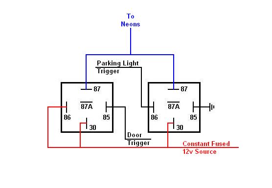
Come on with the door open (negative trigger), and also come on if the parking lights are flipped on (positive trigger).  I know I can do this with two relays, but do I need to use diodes across the coils or anwhere else?

Thanks

Paul

Hoptup32 
Copper - Posts: 87
Copper spacespace
Joined: December 25, 2004
Location: United States
Posted: May 31, 2006 at 9:00 PM / IP Logged  

Here's a simple diagram to use both triggers, no diodes required if you use the same constant 12v fused power source.

Two Triggers, one output -- posted image.

pthermes 
Member - Posts: 3
Member spacespace
Joined: May 31, 2006
Location: United States
Posted: May 31, 2006 at 9:30 PM / IP Logged  

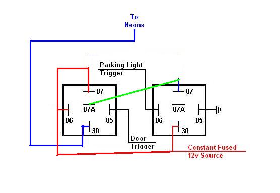
Wouldn't this work also??  Or would this cause some problems?Two Triggers, one output -- posted image.

KPierson 
Platinum - Posts: 3,527
Platinum spaceThis member consistently provides reliable informationspace
Joined: April 14, 2005
Location: Ohio, United States
Posted: June 01, 2006 at 1:31 PM / IP Logged  

You should be able to do it with one relay.

Pin 86 - 12vdc

Pin 85 - (-)Door pin

Pin 30 -(+) 12vdc output to neons

Pin 87A (+)12vdc parking light signal
Pin 87A (+)12vdc

When the door is closed and the parking lights are off no voltage will flow to your neons.

When you open the door it will energize the relay and the 12vdc will run the neons.

If the door is closed and you turn on your parking lights the parking light signal will run the neons.

Kevin Pierson
djfearny2 
Silver - Posts: 810
Silver spaceThis member has made a donation to the12volt.com. Click here for more info.spacespace
Joined: September 23, 2002
Location: United States
Posted: June 01, 2006 at 1:48 PM / IP Logged  
k peirson is right you can do it with one relay however one thing is wrong.
Pin 86 - 12vdc
Pin 85 - (-)Door pin
Pin 30 -(+) 12vdc output to neons
Pin 87A (+)12vdc parking light signal
Pin 87 (+)12vdc (this was the mistake)
Jon
Installer/Help Technician
---coral springs florida---
mecp certification is not always needed. I have it and it has not helped me out at all. my experience out shines it.
KPierson 
Platinum - Posts: 3,527
Platinum spaceThis member consistently provides reliable informationspace
Joined: April 14, 2005
Location: Ohio, United States
Posted: June 01, 2006 at 2:28 PM / IP Logged  

what, your relays don't have two 87As?????? 

Sorry about that.

Kevin Pierson
pthermes 
Member - Posts: 3
Member spacespace
Joined: May 31, 2006
Location: United States
Posted: June 01, 2006 at 5:01 PM / IP Logged  

Thanks for all the replies.  I don't want to do it with one relay because I plan on adding some other items to the circuit and think it would be too much of a draw on the parking light circuit.  

Thanks

KPierson 
Platinum - Posts: 3,527
Platinum spaceThis member consistently provides reliable informationspace
Joined: April 14, 2005
Location: Ohio, United States
Posted: June 01, 2006 at 5:52 PM / IP Logged  

If that is the case I would go with the first diagram.  The 2nd one will work, but its more complicated and tehre is no need to connect the relays together.  For troubleshooting purposes I would keep all relays as seperate as possible.

Kevin Pierson
Page of 2

  Printable version Printable version Post ReplyPost New Topic
You cannot post new topics in this forum
You cannot reply to topics in this forum
You cannot delete your posts in this forum
You cannot edit your posts in this forum
You cannot create polls in this forum
You cannot vote in polls in this forum

  •  
Search the12volt.com
Follow the12volt.com Follow the12volt.com on Facebook
Tuesday, April 16, 2024 • Copyright © 1999-2024 the12volt.com, All Rights Reserved Privacy Policy & Use of Cookies
Disclaimer: *All information on this site ( the12volt.com ) is provided "as is" without any warranty of any kind, either expressed or implied, including but not limited to fitness for a particular use. Any user assumes the entire risk as to the accuracy and use of this information. Please verify all wire colors and diagrams before applying any information.

Secured by Sectigo
the12volt.com spacer
Support the12volt.com
Top
the12volt.com spacer