the12volt.com spacer
icon

Alarm diagram for 2003 Acura TL-S


Post ReplyPost New Topic
< Prev Topic Next Topic >
legend_tl-s 
Member - Posts: 7
Member spacespace
Joined: July 29, 2006
Location: United States
Posted: July 30, 2006 at 6:54 PM / IP Logged  

I've searched this forum for 03 TL-S diagrams, and found some that are for 03 CL-S. is preaty close, but didn't have what I needed.

I have 2003 Acura TL-S w/o navigation. 

Installing Visionguard 6000

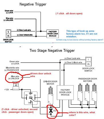
#1       I want to hook up "Two Stage Door Locks" - first click opens drivers door only, second click opens passenger doors. Now I need to find a Driver door motor wire "to cut in with a Drivers Unlock, using a relay of course".  Here is what I am talking about: Alarm diagram for 2003 Acura TL-S -- posted image.

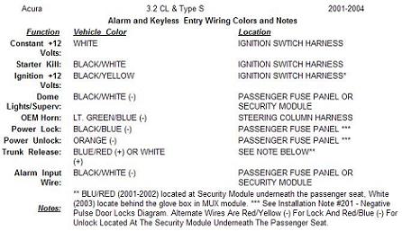
#2        Sounds cheap, but can't find a WHITE/ RED wire for trunk release at module behind glove box. I've looked everywhere in that area and no luck. There is like 10 different WHITE/ red wires. I've tried going off 03 CL-s diagram looking for white wire, still no luck. Can you guys post a picture of this wire that I can tap in, so that my trunk can be opened? I've also look for MUX here is the source: http://https://www.the12volt.com/installbay/forum_posts.asp?tid=29894 Alarm diagram for 2003 Acura TL-S -- posted image.

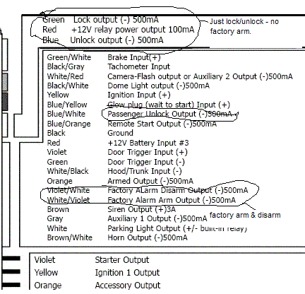
#3      where can I find wire for sunroof, factory arm, disarm,  arm/disarm w/o arming factory system, tachometer wire (found 2 pin connector, blue wire at drivers shock tower with only one blue wire in it. not sure if that is it.) windows...

Alarm diagram for 2003 Acura TL-S -- posted image.

#4       factory alarm armed chirp, can i hook aftermarket alarm to it, and have only factory chirp?

There is a lot of TL guys out there that could use this diagram, so if anyone can help, please...

One BIG THANKS, Eugene

josh1979 
Silver - Posts: 320
Silver spacespace
Joined: July 03, 2006
Location: United States
Posted: July 30, 2006 at 7:41 PM / IP Logged  
12volts white  +  ignition harness
Starter BLACK/ white  +  ignition harness
Second Starter N/A    
Ignition BLACK / YELLOW  +  ignition harness
Second Ignition N/A    
Third Ignition N/A    
Accessory yellow  +  ignition harness
Second Accessory WHITE/ black  +  ignition harness
Keysense blue/white  -  ignition harness
Power Lock BLACK/ blue  -  passenger fuse box
Notes: Located in a blue or gray 22 pin connector in front of the passenger fuse box. Use the key switch in the passenger door to test.
Power Unlock orange  -  passenger fuse box
Notes: Located in a blue or gray 22 pin connector in front of the passenger fuse box. Use the key switch in the passenger door to test.
Lock Motor WHITE/ red  5wi 18 pin grn plug, driver fuse box
Unlock Motor yellow  5wi 18 pin grn plug, driver fuse box
Parking Lights+ RED / black  +  4 pin grn plug top of pass. fuse box
Parking Lights- RED / yellow  -  headlight switch
Hazards same as turn signals    
Turn Signal(L) GREEN/ blue  +  steering column
Turn Signal(R) GREEN/ YELLOW  +  steering column
Reverse Light GREEN/ black  +  2 pin brn plug below pass. fuse box
Door Trigger BLACK/ white  -  4 pin grn plug top of pass. fuse box
Dome Supervision use door trigger    
Trunk/Hatch Pin blue/green  -  18 pin gry plg left of dri. fuse box
Hood Pin yellow  -  lt. blue plug below pass. fuse box
Trunk/Hatch Release WHITE/ red  +  passenger MUX module
Notes: The passenger MUX module is located behind the glove box.
Power Sliding Door N/A    
Factory Alarm Arm arms with lock    
Factory Alarm Disarm disarms with unlock    
Disarm No Unlock BLACK/ red to blue  -  driver door key cylinder in door
Tachometer blue  ac  tach test connector
Notes: The tach test connector is a 2 pin connector near the air intake on the driver side shock tower.
Wait to start N/A    
Brake Wire WHITE/ black  +  brake pedal switch
Parking Brake GREEN/ red  -  lt. blue plug below pass. fuse box
Horn Trigger lt. GREEN/ blue  -  steering column
Memory Seat 1 N/A    
Memory Seat 2 N/A    
Memory Seat 3 N/A    
Alarm diagram for 2003 Acura TL-S -- posted image.
Interface Module:Category:
Immobilizer Bypass
Required:
Yes
Type:
Transponder
Part #: 556HW
Alternate Part1 #: 556UW
Alternate Part2 #: DesignTech 20402
Alternate Part3 #: DesignTech 29402
Notes: When using the 556HW, follow the mode 2 wiring diagram. The reference wire is BROWN / yellow, data 1 wire is red, data 2 wire is blue and ignition wire is yellow/black
bring back the rotary phone so i dont have to press 1 to proceed in english
glantern83 
Member - Posts: 32
Member spacespace
Joined: July 13, 2006
Location: United States
Posted: July 30, 2006 at 7:58 PM / IP Logged  
visit this link and youve got the pic you requested it's th wire that is taped...
http://www.directwholesale.net/diagrams/Images.asp?ImageID=1732&link=BULLDOG
-KITT
legend_tl-s 
Member - Posts: 7
Member spacespace
Joined: July 29, 2006
Location: United States
Posted: July 31, 2006 at 12:33 AM / IP Logged  

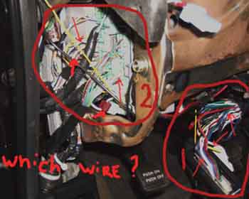
Which wire, in which connector? Zone 1 or 2?

Alarm diagram for 2003 Acura TL-S -- posted image.

Thank you

josh1979 
Silver - Posts: 320
Silver spacespace
Joined: July 03, 2006
Location: United States
Posted: July 31, 2006 at 8:26 AM / IP Logged  
zone 2 the white one with the T tap on it. (i cringe when i see T taps)
bring back the rotary phone so i dont have to press 1 to proceed in english

Sorry, you can NOT post a reply.
This topic is closed.

  Printable version Printable version Post ReplyPost New Topic
You cannot post new topics in this forum
You cannot reply to topics in this forum
You cannot delete your posts in this forum
You cannot edit your posts in this forum
You cannot create polls in this forum
You cannot vote in polls in this forum

  •  
Search the12volt.com
Follow the12volt.com Follow the12volt.com on Facebook
Thursday, March 28, 2024 • Copyright © 1999-2024 the12volt.com, All Rights Reserved Privacy Policy & Use of Cookies
Disclaimer: *All information on this site ( the12volt.com ) is provided "as is" without any warranty of any kind, either expressed or implied, including but not limited to fitness for a particular use. Any user assumes the entire risk as to the accuracy and use of this information. Please verify all wire colors and diagrams before applying any information.

Secured by Sectigo
the12volt.com spacer
Support the12volt.com
Top
the12volt.com spacer