the12volt.com spacer
icon

Adding a power door lock switch


Post ReplyPost New Topic
< Prev Topic Next Topic >
bsd1 
Copper - Posts: 62
Copper spacespace
Joined: August 01, 2006
Location: California, United States
Posted: August 01, 2006 at 5:46 AM / IP Logged  

Car: 95 Nissan 240SX base model

Alarm: Matrix RSX3.5

Factory power door lock: No

My goal: to be able to use the factory power door lock switches (both LH+RH) I obtained from an SE model to toggle lock/unlock.

Below is the door lock section of my Matrix RSX3.5 installed by the installer. He also added two actuators, and two 610T relays.

Adding a power door lock switch -- posted image.

Do I have to purchase 2 additional 451M relays or can I use the existing 610Ts and connect my two wires (broken wires in blue and green) from factory door lock switch to 87a as shown in the pic below:

Adding a power door lock switch -- posted image.
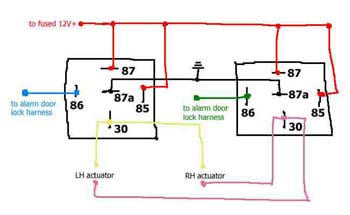
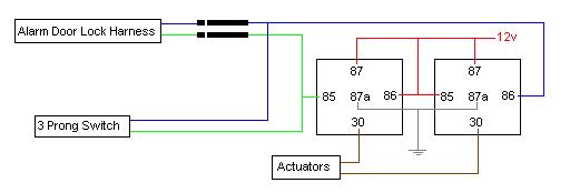
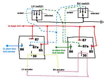
Please note that the switches use ground only and the center pin has solid ground. This wiring is like [url=https://www.the12volt.com/doorlocks/page3.asp#5w]5 Wire Alternating 12 Volts[/url] and a little identical to [url=https://www.the12volt.com/doorlocks/page3.asp#arp]reverse polarity[/url] .

I labeled [b]to alarm door lock harness[/b] because I am not sure it's 12v or ground. When I unpluged the door harness from the brain I got ground when probing the 86s, and got 12v when they are plugged. Anyway, I believe this isn't important to my question in the first place.

What I concern the most is if I can remove the existing ground from 87a (as shown in top pic above) and run the wires from the switches (the broken wires as shown in 2nd pic above) to accomplish my goal.

This thread is pretty much a followup to another thread started by [url=https://www.the12volt.com/installbay/forum_posts.asp?tid=79971&PN=7]crxratedr[/url].

doibuy 
Copper - Posts: 177
Copper spacespace
Joined: March 15, 2006
Posted: August 01, 2006 at 7:36 AM / IP Logged  
Can't follow your diagram that well, but you should tie the lock switches in to the relays where the alarm outputs are at.
captainzab 
Silver - Posts: 606
Silver spaceThis member has made a donation to the12volt.com. Click here for more info.spacespace
Joined: February 09, 2005
Location: United States
Posted: August 01, 2006 at 10:32 AM / IP Logged  
Yes you can connect the wire from the switch directly to the blue and green wire of the clifford, but make sure you add diodes so you do not hurt the alarm.
have the bandside of the diode pointing towards the alarm (neg flow from bandside to non bandside)
bsd1 
Copper - Posts: 62
Copper spacespace
Joined: August 01, 2006
Location: California, United States
Posted: August 01, 2006 at 1:25 PM / IP Logged  
captainzab wrote:
have the bandside of the diode pointing towards the alarm (neg flow from bandside to non bandside)
I don't understand. Which is the bandside, cathode (side with the stripe) or anode (side without the stripe)?
All I know is that the switch sends negative pulse (lock or unlock). Your saying I splice a new wire to the green wire from the brain, then place a diode between this new wire and the wire from the switch?
(A) switch - (cathode)diode(anode) - door harness on brain
(B) switch - (anode)diode(cathode) - door harness on brain
A or B?
Do I connect the green wire from switch of the LH and RH together, then go thru ONE diode then to the brain or do I use TWO diodes, one for each of the two wires for each door, and a total of FOUR diodes for the whole wiring?
Is 1N4001/L diode the correct one?
When wiring, the position of the diode should be closer to the door harness on the brain or the switch?
captainzab 
Silver - Posts: 606
Silver spaceThis member has made a donation to the12volt.com. Click here for more info.spacespace
Joined: February 09, 2005
Location: United States
Posted: August 01, 2006 at 2:45 PM / IP Logged  
i was thinking of placing a diode on the doorlock wire of the alarm (blue and green). Put a diode with the stripe side facing the alarm.
Alarm Brain -----> [ (stripe side closest to brain) diode] ---> meet up with wire from switch --> relay
captainzab 
Silver - Posts: 606
Silver spaceThis member has made a donation to the12volt.com. Click here for more info.spacespace
Joined: February 09, 2005
Location: United States
Posted: August 01, 2006 at 2:48 PM / IP Logged  
Is 1N4001/L diode the correct one?
Yes you can use that
bsd1 
Copper - Posts: 62
Copper spacespace
Joined: August 01, 2006
Location: California, United States
Posted: August 01, 2006 at 3:07 PM / IP Logged  
The green and blue wires from the alarm door harness will be tap spliced anyway. So should the position of diode be closer to the brain or the relay, or does it matter?
You haven't answered the total number of diode required for the whole wiring process, so I guess I need TWO since the alarm locks/unlocks both door at the same time, and the door lock switches should do the same thing.
Using diode really sounds appropriate. Most other replies I have received from elsewhere simply told me to just T it in without diode at all.
You know, the factory switch costed me $70 alone, not to mention the close to $700 Matrix RSX3.5 (with all the addons), I really need to get this wiring right and not messing up my alarm.
bsd1 
Copper - Posts: 62
Copper spacespace
Joined: August 01, 2006
Location: California, United States
Posted: August 01, 2006 at 3:13 PM / IP Logged  
So, messing with 87a like shown in my 2nd pic above and at 5 Wire Alternating 12 Volts Positive Door Locks won't work or you have no experience on 5-wire scheme and unsure?
I came up with the 2nd pic cuz that's what I originally thought of the appropriate way to do it.
captainzab 
Silver - Posts: 606
Silver spaceThis member has made a donation to the12volt.com. Click here for more info.spacespace
Joined: February 09, 2005
Location: United States
Posted: August 01, 2006 at 3:21 PM / IP Logged  
Adding a power door lock switch -- posted image.
bsd1 
Copper - Posts: 62
Copper spacespace
Joined: August 01, 2006
Location: California, United States
Posted: August 01, 2006 at 5:32 PM / IP Logged  
captainzab wrote:
Is 1N4001/L diode the correct one?
Yes you can use that
Thanks alot for the diagram. I will try that out and post the result here as soon as I get some diode, perhaps from http://www.radioshack.com/search/index.jsp?origkw=diode&kw=diode&kwCatid=&pg=1 ?
The first one with catalog number: 276-1101, is this the one? Without the /L, is 1N4001 okay? If I should use another type of diode, please tell me the catalog number.
Page of 4

  Printable version Printable version Post ReplyPost New Topic
You cannot post new topics in this forum
You cannot reply to topics in this forum
You cannot delete your posts in this forum
You cannot edit your posts in this forum
You cannot create polls in this forum
You cannot vote in polls in this forum

  •  
Search the12volt.com
Follow the12volt.com Follow the12volt.com on Facebook
Friday, April 26, 2024 • Copyright © 1999-2024 the12volt.com, All Rights Reserved Privacy Policy & Use of Cookies
Disclaimer: *All information on this site ( the12volt.com ) is provided "as is" without any warranty of any kind, either expressed or implied, including but not limited to fitness for a particular use. Any user assumes the entire risk as to the accuracy and use of this information. Please verify all wire colors and diagrams before applying any information.

Secured by Sectigo
the12volt.com spacer
Support the12volt.com
Top
the12volt.com spacer