the12volt.com spacer
icon

Adding a power door lock switch


Post ReplyPost New Topic
< Prev Topic Next Topic >
captainzab 
Silver - Posts: 606
Silver spaceThis member has made a donation to the12volt.com. Click here for more info.spacespace
Joined: February 09, 2005
Location: United States
Posted: August 04, 2006 at 9:52 AM / IP Logged  
-use electrical tape and tape the diode tips exactly like shown in captainzab's diagram
I usually butt connect a wire & didoe, or solder the diode to the wire then tape something study behind it so the soldier cant break.
-after I reconnected the battery cables I heard the actuator's noise immediately, sound like it was trying to lock or unlock the door repeatedly, without me toggling the switch
If you knew that it was repeatedly trying to push/pull, should have unplug it. But it would seem that your switch is giving the relay ground thus switching on the relay.
I say check your switch again with your DMM. Make sure its not giving ground all the time
bsd1 
Copper - Posts: 62
Copper spacespace
Joined: August 01, 2006
Location: California, United States
Posted: August 04, 2006 at 4:55 PM / IP Logged  
I'd solder and use hot shrink tube for a permament wiring, but I was just testing the connection temporarily.
captainzab, you're the man!! That factory switch I got from junk yard wasn't quite smooth to toggle in one of the two positions, my mistake for not lubricating it in advance. So I can confirm by now that the constant ground for a few seconds killed the motor inside the actuator.
italian_virus 
Copper - Posts: 143
Copper spacespace
Joined: March 26, 2006
Location: Ontario, Canada
Posted: August 04, 2006 at 6:25 PM / IP Logged  
captainzab wrote:
yes, its that simple. But make sure its a 3 wire switch where the center is ground. I know someone out there might go to the junkyard and accidently get a weird 5 wire type that i dont know how it works.
i just checked my switch, and i do have a ground but its not center, would that affect it?
captainzab 
Silver - Posts: 606
Silver spaceThis member has made a donation to the12volt.com. Click here for more info.spacespace
Joined: February 09, 2005
Location: United States
Posted: August 04, 2006 at 8:38 PM / IP Logged  
i just checked my switch, and i do have a ground but its not center, would that affect it?
You can use it. Use your DMM to check for continuity. Press button forward and find your 2 wire that has continity. Press button backward and find your 2 wire that has continuity.
The wire that shows continuity when press forward and backward would be your ground.
italian_virus 
Copper - Posts: 143
Copper spacespace
Joined: March 26, 2006
Location: Ontario, Canada
Posted: August 31, 2006 at 12:26 PM / IP Logged  
bsd1 wrote:
captainzab wrote:
have the bandside of the diode pointing towards the alarm (neg flow from bandside to non bandside)
I don't understand. Which is the bandside, cathode (side with the stripe) or anode (side without the stripe)?
All I know is that the switch sends negative pulse (lock or unlock). Your saying I splice a new wire to the green wire from the brain, then place a diode between this new wire and the wire from the switch?
(A) switch - (cathode)diode(anode) - door harness on brain
(B) switch - (anode)diode(cathode) - door harness on brain
A or B?
Do I connect the green wire from switch of the LH and RH together, then go thru ONE diode then to the brain or do I use TWO diodes, one for each of the two wires for each door, and a total of FOUR diodes for the whole wiring?
Is 1N4001/L diode the correct one?
When wiring, the position of the diode should be closer to the door harness on the brain or the switch?
sorry to bother you guys again, im just trying this out right now, and from what it looks like it did nothing... i had both diodes connected like the diagram, now to i have to have the diodes on both sides for any of this to work out, or just on one side??.. and does it have to be a toggle switch or can it be an on and off switch?. ..
And just so you have a relative idea on how im connecting it... from the actuator comes the diode stripe side facing the actuator, then two connections one going to the switch and the other completing the connection. (using blue and green wires). i have tried to switch the connections of the wiring keeping the ground(used from the actuator) as constant .. and switching the blue and green from the switch.. and still nothing... any idea anyone??
italian_virus 
Copper - Posts: 143
Copper spacespace
Joined: March 26, 2006
Location: Ontario, Canada
Posted: August 31, 2006 at 12:51 PM / IP Logged  
captainzab wrote:
Adding a power door lock switch - Page 3 -- posted image.
i know this may sound dumb but i have to make sure before i start splicing, i would have to cut in to my car alarms (viper) blue and green and make the connection from there.. correct ???
italian_virus 
Copper - Posts: 143
Copper spacespace
Joined: March 26, 2006
Location: Ontario, Canada
Posted: August 31, 2006 at 2:25 PM / IP Logged  
alright guys, i have also now tried from the viper brain itself, putting the cathode towards the brain,using the blue and green wires, and still nothing..
on the back of the viper brain it says that
Blue: (-) Instant Trigger Zone 1
Green: (-) Door Trigger Zone 3
There is also
Violet: (+) Door Trigger Zone 3
BUT the connection for Violet is not connected to anything ;s
help anyone??
bsd1 
Copper - Posts: 62
Copper spacespace
Joined: August 01, 2006
Location: California, United States
Posted: August 31, 2006 at 3:34 PM / IP Logged  
italian_virus wrote:
i had both diodes connected like the diagram, now to i have to have the diodes on both sides for any of this to work out, or just on one side??
Just like the diagram. Two diodes in total for the whole setup.
italian_virus wrote:
and does it have to be a toggle switch or can it be an on and off switch?
It can be virtually any momentary switch with 3 positions: (ON)- OFF - (ON). Just on and off 2 positions won't work because you'd want to lock and unlock the door, not just either one. The ground pulse is also momentary. If your switch stays in the ON position for longer than 1 second, you will blow the actuator. Therefore, it must return to center-off position.
italian_virus wrote:
i have tried to switch the connections of the wiring keeping the ground(used from the actuator) as constant .. and switching the blue and green from the switch.. and still nothing... any idea anyone??
Take out the door panel and smell the actuators, I bet they both burned out.
Nobody ever explained to me the door lock mechanism, but then I finally figured that out myself after trials and errors. I blew two actuators too.
Here's what I can tell you, don't forget:
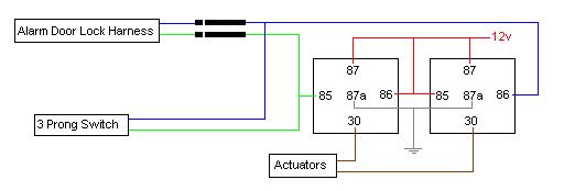
- the actuator needs one ground and one 12v to move, both wires accept ground/12v and both wires rest at ground, because of 87a (normally closed).
- both relays must not energize at the same time. You either lock or unlock, not both. That said, the energize relay will send + pulse to the actuator (pin30 connects to pin87), the other non-energize relay will send - pulse to the actuator (pin30 connects to pin87a).
Simply, - -, or + -, or - +. If you accidentally sends a + - or - + for longer than 1 second, because of using a wrong switch, then say go bye to your actuator and it's time to buy a new one.
italian_virus wrote:
on the back of the viper brain it says that
Blue: (-) Instant Trigger Zone 1
Green: (-) Door Trigger Zone 3
There is also
Violet: (+) Door Trigger Zone 3
The blue and green I've been talking about is from door lock harness, not H1 harness.
italian_virus 
Copper - Posts: 143
Copper spacespace
Joined: March 26, 2006
Location: Ontario, Canada
Posted: September 01, 2006 at 12:27 AM / IP Logged  
Nice thanks man i apprecaite it, i will give it a shot and let you know how it goes, i already have an idea on what was wrong..andd the actuators still work, i connected them again normally and they work, soo im pretty lucky damnn haha, and just ot make sure when u mean h1 harness ur talkin about the alarm brain right?
bsd1 
Copper - Posts: 62
Copper spacespace
Joined: August 01, 2006
Location: California, United States
Posted: September 01, 2006 at 5:52 AM / IP Logged  
italian_virus wrote:
make sure when u mean h1 harness ur talkin about the alarm brain right?
Yes, H1 (12-pin) is the primary harness.
Page of 4

  Printable version Printable version Post ReplyPost New Topic
You cannot post new topics in this forum
You cannot reply to topics in this forum
You cannot delete your posts in this forum
You cannot edit your posts in this forum
You cannot create polls in this forum
You cannot vote in polls in this forum

  •  
Search the12volt.com
Follow the12volt.com Follow the12volt.com on Facebook
Tuesday, April 23, 2024 • Copyright © 1999-2024 the12volt.com, All Rights Reserved Privacy Policy & Use of Cookies
Disclaimer: *All information on this site ( the12volt.com ) is provided "as is" without any warranty of any kind, either expressed or implied, including but not limited to fitness for a particular use. Any user assumes the entire risk as to the accuracy and use of this information. Please verify all wire colors and diagrams before applying any information.

Secured by Sectigo
the12volt.com spacer
Support the12volt.com
Top
the12volt.com spacer