the12volt.com spacer
icon

whats the best way to wire 6 subs


Post ReplyPost New Topic
< Prev Topic Next Topic >
wvsquirrel 
Gold - Posts: 1,237
Gold spaceThis member has made a donation to the12volt.com. Click here for more info.spacespace
Joined: July 27, 2002
Location: Florida, United States
Posted: October 16, 2006 at 6:07 PM / IP Logged  
Depending on what guage wire you use, you may want to consider using a grommit like this one or something similar, then sealing that.
Another option you have instead of drilling the holes inside the box is to add terminals outside the box. Make a new terminal cup for each sub, wire each sub individually like the diagrams, and then wire the cups together. It sounds a little confusing but I can walk you through it with another diagram if you need whats the best way to wire 6 subs - Page 4 -- posted image. Although I think wiring inside the enclosure would look a lot cleaner.
Either way just make sure to pay attention to the diagrams. On several (3) of the subs are turned around (spun not flipped) 180 degrees. Just watch the A's and B's, as well as which voice coil are where *laughing* You definitely picked an interesting sub *laughing*
Squirrel
"No more Cpt. Kirk chit chat"
If its too loud, then you're too old
Donate to the12volt.com
master5 
Silver - Posts: 1,123
Silver spacespace
Joined: October 10, 2006
Location: United States
Posted: October 16, 2006 at 6:40 PM / IP Logged  

Ok squirrel, you did the diagrams when I asked you too, I did the calulations. Not really that difficult but my eyes are tearing just from exhaustion due to working ... lol.

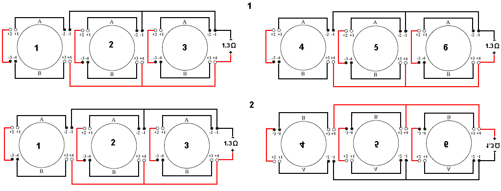
The first diagram shows 3 subs in parallel, the coils wired for 4 onms each. Total load....1.3 ohms..you were darn close for a novice and this setup would have the same rules basically has if it were 1ohm..could still be used.(assuming a 1 ohm stable amp.)

The secong diagram shows the same basic setup but another set of 3 wired parallel to the other set of 3. Just divide in half you get a total load of .65 ohms, you had .5 but still close considering.

the third diagram looks to me to be the same as the first...a mirror image but the colors of the wires are reversed so no effect on the load.

The 4th diagram would not work right so I didn't bother solving it. You can't wire voice coils differently when connecting subs to the same channel of an amp. well phisically you could but the speaker(s) in parallel that had lower ohms would be getting more power then the ones in serires (or with higher ohms value). So some subs would be jumping out of thier baskets, while some would be not doing much. Add to that a lower output from cancellation. hope I explained that technically correct.

but overall great job. glad you have the patience, i would have to charge to do diagrams like that because it would take all day.

wvsquirrel 
Gold - Posts: 1,237
Gold spaceThis member has made a donation to the12volt.com. Click here for more info.spacespace
Joined: July 27, 2002
Location: Florida, United States
Posted: October 16, 2006 at 6:48 PM / IP Logged  
Thx Master5.
Take a "closer" look at the 3rd diagram and I think you'll be suprised whats the best way to wire 6 subs - Page 4 -- posted image. You'll notice that the right (3) subs are rotated 180 degrees, as are the voice coils. That's why the colors are opposite, because it's positive to negative. Also look at the voice coil numbering and the A's and B's. whats the best way to wire 6 subs - Page 4 -- posted image. Basically take the 2nd diagram and turn the right-most 3 subs upside down on the paper.
That was my way of showing the (2) banks of 3 wired at 1.3 ohms, and then wired in Series. It still might not be correct, but it's worth another look.
I understand what you mean about number 4. I was worried about that. Oh well, it was still fun to try!
Squirrel
"No more Cpt. Kirk chit chat"
If its too loud, then you're too old
Donate to the12volt.com
master5 
Silver - Posts: 1,123
Silver spacespace
Joined: October 10, 2006
Location: United States
Posted: October 16, 2006 at 7:04 PM / IP Logged  

ahhh..ok now I see. Still has a problem as the left bank is wired differently then the right, then paralled together. Similar problem as with diagram 4...the bank with the lowest ohm value will get more power.

I will try to simplfy this by just using the schematics from DMX. Maybe you can work out a better diagram. Ok, they show 3 possible scenerios. 1 ohm,2 ohm and 4ohm. Now I will work something out assuming a 1ohm stable amp. If the amp is 2 ohm stable let me know and I will do another.

Use the sub diagram for the 2ohm wiring. Put a bank of 3 in parallel. That will give us a total load of .66 ohms. Now do the same for the right bank  (also .66)  series both those banks and you have a total ohms load of 1.2ohms...just about on the money.

There may be other configs. that can work as well but for now we can use this. I am hoping someone else can try it also.

Peace

wvsquirrel 
Gold - Posts: 1,237
Gold spaceThis member has made a donation to the12volt.com. Click here for more info.spacespace
Joined: July 27, 2002
Location: Florida, United States
Posted: October 16, 2006 at 7:11 PM / IP Logged  
Actually the left and right banks are both wired the same on each side. They are just connected together in Series instead of Parallel. I'll post a pic so you can see what I did.
Squirrel
"No more Cpt. Kirk chit chat"
If its too loud, then you're too old
Donate to the12volt.com
wvsquirrel 
Gold - Posts: 1,237
Gold spaceThis member has made a donation to the12volt.com. Click here for more info.spacespace
Joined: July 27, 2002
Location: Florida, United States
Posted: October 16, 2006 at 7:37 PM / IP Logged  
Ok lets see if this helps to clarify what I did in the diagram...
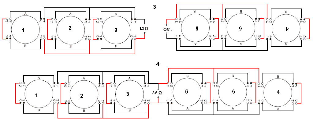
Step 1: Both Left and Right banks are wired identically into 1.3ohms
Step 2: The Right bank is flipped vertically (no change to the wiring)
Step 3: The Right bank is flipped horizontally (no change to the wiring)
Step 4: The numerical and alphabetical values are simple turned the right way so you can read them. All connections are wired identically on both banks, and both banks are wired together in Series.
Is this still incorrect now that I've shown that both banks are identical?
whats the best way to wire 6 subs - Page 4 -- posted image.
Squirrel
"No more Cpt. Kirk chit chat"
If its too loud, then you're too old
Donate to the12volt.com
wvsquirrel 
Gold - Posts: 1,237
Gold spaceThis member has made a donation to the12volt.com. Click here for more info.spacespace
Joined: July 27, 2002
Location: Florida, United States
Posted: October 16, 2006 at 7:48 PM / IP Logged  
I think I did screw up the Series diagram. I'm working on another one now that should be right (or at least more readable)
Squirrel
"No more Cpt. Kirk chit chat"
If its too loud, then you're too old
Donate to the12volt.com
wvsquirrel 
Gold - Posts: 1,237
Gold spaceThis member has made a donation to the12volt.com. Click here for more info.spacespace
Joined: July 27, 2002
Location: Florida, United States
Posted: October 16, 2006 at 7:51 PM / IP Logged  
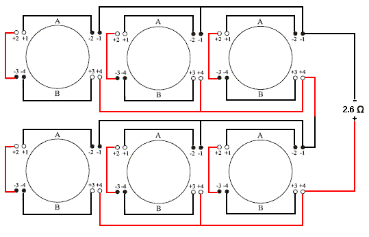
Ok, this one is MUCH EASIER to see...
whats the best way to wire 6 subs - Page 4 -- posted image.
If it is correct then I'll repost the main pic with the 3 correct wiring methodoligies
Sorry for all teh pics, I know it's gotta be getting confusing for everyone!
Squirrel
"No more Cpt. Kirk chit chat"
If its too loud, then you're too old
Donate to the12volt.com
wvsquirrel 
Gold - Posts: 1,237
Gold spaceThis member has made a donation to the12volt.com. Click here for more info.spacespace
Joined: July 27, 2002
Location: Florida, United States
Posted: October 16, 2006 at 8:02 PM / IP Logged  
Here's a modified version of the original number 2. I see where I screwed up on the original...
whats the best way to wire 6 subs - Page 4 -- posted image.
Squirrel
"No more Cpt. Kirk chit chat"
If its too loud, then you're too old
Donate to the12volt.com
wvsquirrel 
Gold - Posts: 1,237
Gold spaceThis member has made a donation to the12volt.com. Click here for more info.spacespace
Joined: July 27, 2002
Location: Florida, United States
Posted: October 16, 2006 at 8:04 PM / IP Logged  
The same steps apply to the remodified number 2 diagram as the original one though. Watch how the speakers and voice coils are oriented in the diagram!
Squirrel
"No more Cpt. Kirk chit chat"
If its too loud, then you're too old
Donate to the12volt.com
Page of 5

  Printable version Printable version Post ReplyPost New Topic
You cannot post new topics in this forum
You cannot reply to topics in this forum
You cannot delete your posts in this forum
You cannot edit your posts in this forum
You cannot create polls in this forum
You cannot vote in polls in this forum

  •  
Search the12volt.com
Follow the12volt.com Follow the12volt.com on Facebook
Thursday, April 25, 2024 • Copyright © 1999-2024 the12volt.com, All Rights Reserved Privacy Policy & Use of Cookies
Disclaimer: *All information on this site ( the12volt.com ) is provided "as is" without any warranty of any kind, either expressed or implied, including but not limited to fitness for a particular use. Any user assumes the entire risk as to the accuracy and use of this information. Please verify all wire colors and diagrams before applying any information.

Secured by Sectigo
the12volt.com spacer
Support the12volt.com
Top
the12volt.com spacer