the12volt.com spacer
icon

Fade on, Fade off Interior lights


Post ReplyPost New Topic
< Prev Topic Next Topic >
haemphyst 
Platinum - Posts: 5,054
Platinum spaceThis member has been recognized as an authority in Electrical Theory. Click here for more info.spaceThis member has been recognized as an authority in Mobile Audio and Video. Click here for more info.spacespace
Joined: January 19, 2003
Location: Michigan, Bouvet Island
Posted: November 01, 2006 at 5:11 PM / IP Logged  
I built a couple and I couldn't come up with anything that'd do wat you wanted. PWM is what you're left with, I think.
Sorry, I've failed... Fade on, Fade off Interior lights - Page 5 -- posted image.
It all reminds me of something that Molière once said to Guy de Maupassant at a café in Vienna: "That's nice. You should write it down."
kymadan 
Member - Posts: 39
Member spacespace
Joined: March 25, 2006
Location: United States
Posted: November 01, 2006 at 5:28 PM / IP Logged  
You never fail.... You just found another way that wont work! Fade on, Fade off Interior lights - Page 5 -- posted image.
KPierson 
Platinum - Posts: 3,527
Platinum spaceThis member consistently provides reliable informationspace
Joined: April 14, 2005
Location: Ohio, United States
Posted: November 01, 2006 at 6:20 PM / IP Logged  
I think I got it.  Give me a few minutes and I'll post up a drawing.  However, I cheated and expanded the list of materials availible.  All parts are availible at Radioshack, so I consider it 'basic'.
Kevin Pierson
KPierson 
Platinum - Posts: 3,527
Platinum spaceThis member consistently provides reliable informationspace
Joined: April 14, 2005
Location: Ohio, United States
Posted: November 01, 2006 at 6:57 PM / IP Logged  

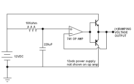
Fade on, Fade off Interior lights - Page 5 -- posted image.

Theory of operation:

When 12vdc is applied the resistor slowly charges the capacitor.  As the cap slowly charges the voltage at the resistor/capacitor junction slowly rises.  The 741 op amp is used for its super high impedance (doesn't put a load on the circuit).  The op amp is configured in a voltage follower configeration, meaning whatever voltage goes in comes out the output.  In between the output of the op amp and the feedback there is a transistor circuit that is designed to simply amplify the low current signal coming from the op amp.  With the transistors in this configuration they will amplify the current of the applied analog voltage.  Be careful and note that the emitters are drawn in a strange way (I mixed it up the first time I used that circuit).  Because the transistors are inside the feedback loop they have virtually no effect on the operation of the op amp.  What you have coming out of the op amp is a voltage that slowly rises to near battery level (it will never actually reach battery level though, one downside to the op amp) with enough current to drive your light.

So, in the end, I used an RC circuit to drive a transistorized buffer that will dim the light on.  Now, interfacing that with the rest of the circuit is going to be another challange.

Kevin Pierson
KPierson 
Platinum - Posts: 3,527
Platinum spaceThis member consistently provides reliable informationspace
Joined: April 14, 2005
Location: Ohio, United States
Posted: November 01, 2006 at 7:01 PM / IP Logged  

Oh, and I simulated this in Electronics Workbench, so it should work.

I didn't put part numbers on the transistors either, the top one is an NPN and the bottom one is a PNP.  Depending on the current requirements you could go with a 2n3904/2n3906 (if under 200mA).  Over 200mA you'll have to find bigger transistors.

Kevin Pierson
master5 
Silver - Posts: 1,123
Silver spacespace
Joined: October 10, 2006
Location: United States
Posted: November 01, 2006 at 8:37 PM / IP Logged  

Impressive, might actually inspire me to get the parts and try it out. Thanks

As far as mspaint I could use some colors but the diagrams would still look like stick figures, just in color. For circuits like above this is fine but I kinda like the "cartoony" looking ones for more basic stuff. I am very artistic, but can't draw that well. Perhaps something to do with being a lefty.

KPierson 
Platinum - Posts: 3,527
Platinum spaceThis member consistently provides reliable informationspace
Joined: April 14, 2005
Location: Ohio, United States
Posted: November 01, 2006 at 9:03 PM / IP Logged  
If I had some free time I would try it out myself, but I'm super busy these days.  It would be cool if someone did test it out!  I'm sure you would need to tweet the values I gave, but they should be close enough to provide some sort of fade on (Electronic Workbench showed about 6 seconds to fully charge).
Kevin Pierson
kymadan 
Member - Posts: 39
Member spacespace
Joined: March 25, 2006
Location: United States
Posted: November 02, 2006 at 2:10 AM / IP Logged  

Hey guys, do you think this would work okay? I  I know it will need to be adjusted here and there, but for the most part it looks good to me. Basically, what it is supposed to do is take approximately 6 seconds to fully fade on. (Thanks KPierson for the diagram!) Then when the domelight wire ceases to  power the circuit, it will drain the 300,000 uf cap and the 220,000 uf cap, and will fade off for approximately 7 seconds. Which in turn is the fade on-fade off circuit I have been trying to figure out.

Fade on, Fade off Interior lights - Page 5 -- posted image.

Now as far as trying to get it to stay on for a couple seconds, it will do that as well approx. 4 seconds. Which will be fine. I have a switch inside the truck to keep it on longer if I need to.

master5 
Silver - Posts: 1,123
Silver spacespace
Joined: October 10, 2006
Location: United States
Posted: November 02, 2006 at 1:27 PM / IP Logged  

Looks good to me. There will also be a slight v-drop through the diodes barrier voltage (if I remember correct it's .7 for ge and  .3 for si) but without actually building/testing this circuit I don't have the abilty to predict the time length/brightness loss with any great accuracy.

The parts are not expensive so you might want to build it and post the results. I am curious myself.

Good luck

kymadan 
Member - Posts: 39
Member spacespace
Joined: March 25, 2006
Location: United States
Posted: November 02, 2006 at 4:13 PM / IP Logged  
How about circuit boards? Anybody know of a good place to get them?
Page of 7

  Printable version Printable version Post ReplyPost New Topic
You cannot post new topics in this forum
You cannot reply to topics in this forum
You cannot delete your posts in this forum
You cannot edit your posts in this forum
You cannot create polls in this forum
You cannot vote in polls in this forum

  •  
Search the12volt.com
Follow the12volt.com Follow the12volt.com on Facebook
Tuesday, April 23, 2024 • Copyright © 1999-2024 the12volt.com, All Rights Reserved Privacy Policy & Use of Cookies
Disclaimer: *All information on this site ( the12volt.com ) is provided "as is" without any warranty of any kind, either expressed or implied, including but not limited to fitness for a particular use. Any user assumes the entire risk as to the accuracy and use of this information. Please verify all wire colors and diagrams before applying any information.

Secured by Sectigo
the12volt.com spacer
Support the12volt.com
Top
the12volt.com spacer