the12volt.com spacer
icon

2001 Ram, Code Alarm CA670


Post ReplyPost New Topic
< Prev Topic Next Topic >
abadv8 
Member - Posts: 37
Member spacespace
Joined: October 10, 2006
Posted: November 04, 2006 at 9:41 PM / IP Logged  
Hi all,
I'm back with another seemingly rediculous question. Shaggy solved my last problem, and I most definately owe him thanks for that. The next question I have is about my door locks and this particular remote start/keyless system (Code Alarm's CA670)...
There is a lot of talk about hooking up relays to switch the polarity for locking and unlocking. My alarm manual gives the choice of either "Negative Lock/Positive Unlock" or "Negative Unlock/Positive Lock". So, can I skip all this stuff with adding extra relays for 5wire actuators? And, if I tap into the wires coming from the central timer module can I just set the alarm for "Negative Unlock/Positive Lock" and call it good?
I'm having a little difficulty figuring this out. I'm guessing the 5wire actuators contain actual rotary motors, where as the "old" style actuators are simply dual throw solenoids.
Thanks again for all the help.
Sean
Twelvoltz 
Platinum - Posts: 2,384
Platinum spaceThis member has made a donation to the12volt.com. Click here for more info.spaceThis member consistently provides reliable informationspace
Joined: March 24, 2005
Location: New Jersey, United States
Posted: November 04, 2006 at 9:59 PM / IP Logged  
Those outputs are just transistorized outputs. These are only strong enough to drive relays, not actuators.
If your truck came with factory keyless entry, you could use the positive lock wire for lock without adding a relay, but the unlock would require a 5-wire. If your truck did not come with factory keyless entry then your need to use 2 relays and 5-wire both lock and unlock.
abadv8 
Member - Posts: 37
Member spacespace
Joined: October 10, 2006
Posted: November 04, 2006 at 10:03 PM / IP Logged  
Thanks Twelvoltz,
So, I am stuck adding in a relay reguardless. I think what I'm missing here is that the manual leads me to believe that that it sends a positive pulse for the lock signal, and a negative pulse for the unlock. Is this incorrect? In any event I guess I will be adding a relay... as everyone else has done.
Thanks again.
Sean
abadv8 
Member - Posts: 37
Member spacespace
Joined: October 10, 2006
Posted: November 23, 2006 at 11:19 PM / IP Logged  
Ok,
I'm relatively competent in electronics. Although, I must say that my area of expertise is mechanical engineering. For some reason I'm having a really difficult time figuring out this 5-wire thing. I have a 2001 Dodge Ram. DEI says I need a positive pulse on the lock wire and a 5-wire on the unlock wire. I thought the unlock wire needed to have a negative pulse applied. I don't really understand why I would need the 5-wire on the unlock side since my remote start system door lock outputs are switchable from pos-lock/neg-unlock to neg-lock / pos-unlock.
So, does the unlock wire need +12v applied to it in order to work? Or am I doing the engineer thing and over analyzing here?
When shown a glass half full of water, three different people had three different responses:
The optimist said, "The glass is half full"
The pessimist said, "The glass is half empty"
The engineer said, "The glass is twice as big as it needs to be"
So, can someone tell me exactly what should be going on here? Or am I just looking for a way to simplify it?
Any help will be appreciated,
Sean    
thepencil 
Gold - Posts: 1,526
Gold spacespace
Joined: December 16, 2002
Location: Canada
Posted: November 24, 2006 at 12:39 AM / IP Logged  
I am not an engineer and I don't understand why Dodge would design such a system either. However, I do know a bit of the basic to move you futher head.
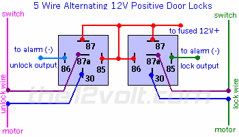
Basically, you have a few sistuation which can encompass such a design. You have a great switch design on the door supplying both positive and negative. In this case you have a positive switch system that supplies a constant +12V. To activate the lock, you click on the switch, the actuator is instantly supplied with +12V to one side of the wire. In order to make the actuator work it will need a +12V and a -12V.   Since one side of the wire on the actuator has a constant ground. When the other side receive +12V it would then move the actuator in one of the direction. In this case it moves in the direction of the Lock setting. On the unlock setting you have to move the polarity on the wire in the opposite direction. Since one side of the actuator rest on ground, you are basically using the relay to reverse one side of the wire. The Door locks diagram on the side would probably help explain this part better than I can.   Have a look there.
Be careful whose advice you buy, but be patient with those who supply it.2001 Ram, Code Alarm CA670 -- posted image.
abadv8 
Member - Posts: 37
Member spacespace
Joined: October 10, 2006
Posted: November 24, 2006 at 1:41 AM / IP Logged  
Thank You,
I still don't completely understand the 5-wire setup on only one side. Am I somewhat close in thinking that the unlock wire needs the relay, and the lock wire does not? Does this mean if I tap in at the central timer module I can use a single relay for this funstion? Or, am I better off just building assembling the two relays as shown and hooking them up?
Oh, I just did some further research and found that the alarm is either pos-lock / pos-unlock or neg-lock / neg-unlock. The polarity change is done by how the two wires are attached. So, for simplicity's sake, this is a standard negative pulse system.
I'm thinking now that I can simply build a two relay, 5-wire assembly and wire it in at the central timer module.
Thank you DiamlerChrysler for making this way more involved than it needs to be.
So, does my (your) approach sound decent?
Thanks again,
Sean
KarTuneMan 
Platinum - Posts: 7,056
Platinum spaceThis member has made a donation to the12volt.com. Click here for more info.spaceThis member consistently provides reliable informationspace
Joined: December 14, 2004
Location: Isle Of Man
Posted: November 24, 2006 at 2:30 PM / IP Logged  
2001 Ram, Code Alarm CA670 -- posted image.
abadv8 
Member - Posts: 37
Member spacespace
Joined: October 10, 2006
Posted: November 26, 2006 at 2:18 PM / IP Logged  
Hello All,
I just installed a CodeAlarm CA670 in a 2001 Dodge Ram Diesel. I've got most everything hooked up on this alarm as I would like it to be. Everything is soldered ,shrink wrapped, and wire tied as per my personnal prefference. So, I'm just about done with the install. I have one major problem though. I used the dome trigger on the headlight switch to serve as my door trigger. This is what the install manual said to do. However, it doesn't seem to be working. What does every one else do on this type of setup? I think I read something about grabbing the door triggers at the central timer module, but I can't find it now.
Thanks for your help
KarTuneMan 
Platinum - Posts: 7,056
Platinum spaceThis member has made a donation to the12volt.com. Click here for more info.spaceThis member consistently provides reliable informationspace
Joined: December 14, 2004
Location: Isle Of Man
Posted: November 26, 2006 at 3:11 PM / IP Logged  
 DOORPIN Yellow In white plug in driver's kick   - 
abadv8 
Member - Posts: 37
Member spacespace
Joined: October 10, 2006
Posted: November 27, 2006 at 12:36 AM / IP Logged  
Got it...
I read the install manual wrong. I also assumed something that i should not have. Fortunately the fuse did its job. I hooked the positive door trigger to the dome light trigger at the headlight switch. I put my DVOM on the wire and it showed .255 volts with door open, so I assumed it was not a negative system. I also assumed that since the dome trigger from the alarm was set to positive polarity, as per the instructions, that the wire was a positive signal. I looked again today, and that's when I found the blow fuse in the alarm brain. So, I set it for negative polarity, and used the negative door trigger from the brain. It works as it should now.
I thought I would post a solution since people seem to be in a bad habbit of just taking the advice and providing no feedback if the adivce worked. You have to assume it did most of the time because they didn't post about their issue again.
Anyways... Thank you all for your help. This site is an asset to novice installers like myself, and if it weren't for sites like this I think a lot of people would be hopelessly lost. But, again, thank you all.
Sean
Page of 2

  Printable version Printable version Post ReplyPost New Topic
You cannot post new topics in this forum
You cannot reply to topics in this forum
You cannot delete your posts in this forum
You cannot edit your posts in this forum
You cannot create polls in this forum
You cannot vote in polls in this forum

  •  
Search the12volt.com
Follow the12volt.com Follow the12volt.com on Facebook
Friday, April 19, 2024 • Copyright © 1999-2024 the12volt.com, All Rights Reserved Privacy Policy & Use of Cookies
Disclaimer: *All information on this site ( the12volt.com ) is provided "as is" without any warranty of any kind, either expressed or implied, including but not limited to fitness for a particular use. Any user assumes the entire risk as to the accuracy and use of this information. Please verify all wire colors and diagrams before applying any information.

Secured by Sectigo
the12volt.com spacer
Support the12volt.com
Top
the12volt.com spacer