the12volt.com spacer
icon

Gentex Mirror Wiring Diagram


Post ReplyPost New Topic
< Prev Topic Next Topic >
unbwogable 
Member - Posts: 1
Member spacespace
Joined: May 11, 2004
Posted: May 11, 2004 at 4:29 PM / IP Logged  

I have a Gentex with 5 pins, no harness. Any suggestions? I'm going to attempt to use the info already provided on this forum. Wish me luck all... If I blow this sucker up I'll post some links to pictures..

-Bryan

rrrfoma 
Member - Posts: 5
Member spacespace
Joined: June 25, 2004
Location: Canada
Posted: June 25, 2004 at 11:14 PM / IP Logged  

Hi,

Does anybody know if it is possible to re-use an existing vehicle t-probe for Gentex mirror?

What modifications are required (I assume resistance must be changed) ?
What are original Genex t-probe parameters?

I fogot to mention - I'm using GNTX-261 and GNTX-177.

Thanks in advance!

rboc 
Member - Posts: 3
Member spacespace
Joined: July 15, 2004
Location: United States
Posted: July 15, 2004 at 12:14 PM / IP Logged  
Gentleman wrote:
The Gentex mirror I had seemed diffrent from what you are describing, it did not have the autoheadlight feature, it had 7 pins but only 5 wires as such:
1 Dark Blue    12V + Ignition
2 black        Ground
3 Violet       Back Up Lamp Connection
4 White        Side View Mirror +
5 Yellow       Side Vie Mirror -
4&5 were used to control side view mirrors that had a dimming feature.
Sorry I could not help
rboc 
Member - Posts: 3
Member spacespace
Joined: July 15, 2004
Location: United States
Posted: July 15, 2004 at 12:20 PM / IP Logged  
I got a Gentex-120 from a '97 Cadillac STS.  Mine came with a separate "black box" that was fastened to the windshield with double face tape (factory stuff).  When I hook power and ground, I get the mirror to work, but the compass is stuck on N.  Is the extra box part of the compass? 
Does anyone know the proper wiring to connect these two devices?

Thanks for any help you can provide!

Robin Masters 
Member - Posts: 2
Member spacespace
Joined: July 21, 2004
Location: Mexico
Posted: July 21, 2004 at 2:25 AM / IP Logged  

Try to calibrate it, if the problem persist maybe the "compass module" is damaged, the separate "extra box" is not a part of the mirror,  but I don´t known how it works.

Sorry for the spelling but my English is not good. if you have more questions maybe I can help you. 

Gentex Mirror Wiring Diagram - Page 7 -- posted image.

backinblack_gp 
Member - Posts: 21
Member spacespace
Joined: March 07, 2004
Location: United States
Posted: July 21, 2004 at 5:21 PM / IP Logged  

Just to add some helpful wiring info for here...

(Chrysler) Gentex GNTX-101 Mirror wiring: (From left to right as you face the back of the mirror)

WHT/RED - +12vdc accessory input

BLK - Chassis ground

BLU/BLK - +12vdc reverse lamps input.  (Ground if not using)

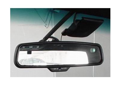
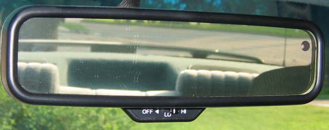
Here is the mirror in question:

Gentex Mirror Wiring Diagram - Page 7 -- posted image.

backinblack_gp 
Member - Posts: 21
Member spacespace
Joined: March 07, 2004
Location: United States
Posted: July 21, 2004 at 5:26 PM / IP Logged  

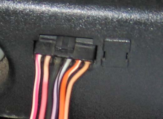
Now, I also have a Chrysler GNTX-104 with no wiring info...

Gentex Mirror Wiring Diagram - Page 7 -- posted image.

The 2-pin temp probe connector is shown to the right under the plastic cover.  This unit apparently utilizes 2 foreward facing photoresistors to enable the high-beam disable function which I would like to use.

Does anyone have the wiring information for this one???

Thanks!

backinblack_gp 
Member - Posts: 21
Member spacespace
Joined: March 07, 2004
Location: United States
Posted: July 21, 2004 at 8:05 PM / IP Logged  

I didn't see the GNTX-126 listed, but here's what I know about it...

General Motors wiring as read from left to right while looking at the back of the unit:

BRN - +12vdc accy

BLK - Chassis ground

GRN - +12vdc reverse light input

GRY - (Unknown)

PNK - (Unknown)

backinblack_gp 
Member - Posts: 21
Member spacespace
Joined: March 07, 2004
Location: United States
Posted: July 23, 2004 at 5:41 PM / IP Logged  

Update on the GNTX-126...

GRY = +Output to side dimming mirror

PNK = -Output to side dimming mirror

Update on the GNTX-104 pictured a few posts ago:

WHT/RED = Accessory +12vdc

PNK = Constant +12vdc

BLK = Ground

VIO/BLK = +12vdc reverse inhibit input

ORG/WHT = Active low transistor output from auto headlights function

BRN = Second active low transistor output from auto headlights function

Hopefully others can benefit from this information.

rasal 
Member - Posts: 1
Member spacespace
Joined: July 25, 2004
Location: United States
Posted: July 25, 2004 at 2:52 PM / IP Logged  

I recently purchased a gntx-177 mirror supposedly from a GM product.  The wiring harness was cut but the wires from the mirror are red, black, white, blank, blank, light green and light green.  The mirror is auto dimming, temp and compass.  I also need the wiring harness and temperature sensor.  Any assistance on wiring and obtaining parts is appreciated.

rasal

Page of 8

  Printable version Printable version Post ReplyPost New Topic
You cannot post new topics in this forum
You cannot reply to topics in this forum
You cannot delete your posts in this forum
You cannot edit your posts in this forum
You cannot create polls in this forum
You cannot vote in polls in this forum

  •  
Search the12volt.com
Follow the12volt.com Follow the12volt.com on Facebook
Friday, April 19, 2024 • Copyright © 1999-2024 the12volt.com, All Rights Reserved Privacy Policy & Use of Cookies
Disclaimer: *All information on this site ( the12volt.com ) is provided "as is" without any warranty of any kind, either expressed or implied, including but not limited to fitness for a particular use. Any user assumes the entire risk as to the accuracy and use of this information. Please verify all wire colors and diagrams before applying any information.

Secured by Sectigo
the12volt.com spacer
Support the12volt.com
Top
the12volt.com spacer