the12volt.com spacer
icon

Aux Input for an Older Delco Radio


Post ReplyPost New Topic
< Prev Topic Next Topic >
mickstan_vr 
Member - Posts: 16
Member spacespace
Joined: November 27, 2006
Location: United States
Posted: November 28, 2006 at 8:53 PM / IP Logged  

I tried to post this last night, but for some reason it didn't work.

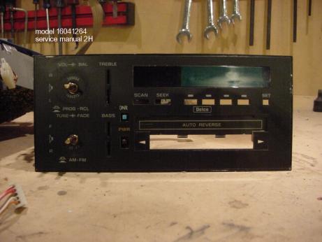
Hello. This is my first post here(second now). I've been all over the internet and joined at least half a dozen groups and cannot find out an answer to this. I have a Delco am/fm cassette from a 1988 Chevrolet Celebrity Eurosport VR. The model number is 16041264. Servivice Manual 2H. Its a regular ol' factory stereo from any number of late 80's GM cars. I want to put an AUX 1/8(3.5mm) stereo plug in it to play my iPod through. I have 2 of these stereos torn apart on my workbench right now that I've been tinkering with for quite a long time.

I know this can be done as there is now a person on ebay selling the modified radios with the input plug. Here is his description : "It has been bench tested with all repairs being made as needed, including replacement of all burned out illumination bulbs. It then had a 3.5mm aux input jack installed in the faceplate, which is a direct link to the amp, with all new electrical connections soldered inplace for dependability. The unit now has the ability to play virtually any portable music device which features a headphone jack and without having to rely on a fm transmitter cassette adapter, or dummy cassette. All of the radio and tape functions perform just like a stock unit and work perfect as well as the control knobs and buttons. Here is how the aux jack works. When you put the 3.5 mm plug into the jack from your IPOD, MP3, or portable CD player, it cuts the radio signal going to the amp. Which allows the signal from your device to play through the radio's amp and then to your speakers."

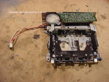
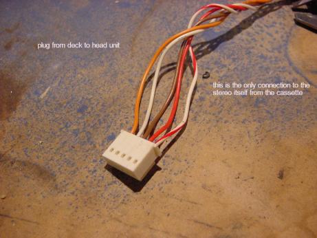
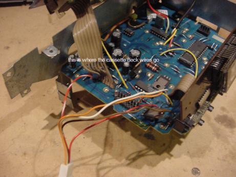
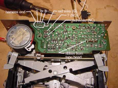
I'm assuming he's cutting the feed from the radio and replacing it with the feed from the 3.5mm plug at the cassette deck. Thereby fooling the amp into thinking its being fed by the cassette signal. I figured out how to cut the radio signal, but can't get a signal from the mp3 player. There are 5 wires connecting the tape deck to the rest of the stereo RD, R/W,BRN,OR,and W. I put a switch in the red wire. That cuts the radio signal going back to the amp in the RED / white wire. I spliced into the other 3 wires with a 3.5 stereo receptecle. When the switch is thrown, it cuts the radio signal, and should allow the mp3 signal to pass to the amp. Should being the key word.  So I put the switch in the R/W wire. Now I get a signal, but its overpowering the amp. The speakers only "thump" the bass line of a song.  So I then put some 100uF caps on what I think are the 2 channels from the iPod that I spliced into. The music is now there, but is weak, and I'm getting noise from the tape head I believe. Heres some pictures if that will help.

Aux Input for an Older Delco Radio -- posted image.

Aux Input for an Older Delco Radio -- posted image.

Aux Input for an Older Delco Radio -- posted image.

Aux Input for an Older Delco Radio -- posted image.

This has GOT to be a simple mod, but I have absolutely no experience at this stuff, nor proper equipment. Ideas?     Anyone????

master5 
Silver - Posts: 1,123
Silver spacespace
Joined: October 10, 2006
Location: United States
Posted: November 29, 2006 at 3:17 AM / IP Logged  

I have never attempted this before..probably because the mp3 technology is relativly new..so no real demand. Basically I am in the business to install and SELL. So if a unit comes in that is not compatable..it is an easy sale to upgrade to a unit with mp3 inputs instead of modifying a 20 year old delco tape deck. However, on a newer model with a nicer head unit..it might be something worth attempting..we all know how lousy FM mods sound.

But, I respect anyone willing to perform custom unique stuff and will tell you how I would attept this.

ok..we know a tape head adaptor works. So all we need to do is connect to the tape head left and right audio signal wires behind the tape head..and somehow get the head unit to switch to tape mode.

Try to find the wire(s) on the switch that switches the deck to tape mode and check with a meter what signal is on the wire(s)...don't forget to ground the shields or expect hum. If you can't get it to switch to tape mode by using the plug itself..install a switch or relay..or perhaps you can modify an exsisting switch or button on the delco to perform this function. Seems simple to me. I had a delco lying around but I just installed it into one of my old cars I am selling.

Next delco I come across (I do often but usually toss them out..have no real use) I might attempt this myself for giggles. If I can get it to work before you do I will post back what I find.

Best of Luck and keep at it.

i am an idiot 
Platinum - Posts: 13,667
Platinum spaceThis member consistently provides reliable informationspace
Joined: September 21, 2006
Location: Louisiana, United States
Posted: November 29, 2006 at 8:25 AM / IP Logged  

You are on the right track with your approach  the only problem I see with Master's plan  is that the cassete head has an output in the microvolt range and you MP3 has probably about 1 volt  output.   We will have to find a place to tap in after the Head amplifier,

I will look around at work to see if I have a deck of this type and will post tonight.

master5 
Silver - Posts: 1,123
Silver spacespace
Joined: October 10, 2006
Location: United States
Posted: November 29, 2006 at 7:56 PM / IP Logged  

If tapping off the tape head was a problem why do the casette adaptors? Regardless, if there was an issue with too much input voltage we could take the guts out of an adjustable LOC (or maybe just a simple resistor)and put it somewhere inside the head unit..theres really to much to them.

Theres no real guarantee that doing after the head amp will not have problems either..and then finding a way to switch the source as well..but I do agree that is another approach..I was looking for the simplest way that has no reason not to work.

mickstan_vr 
Member - Posts: 16
Member spacespace
Joined: November 27, 2006
Location: United States
Posted: November 29, 2006 at 9:34 PM / IP Logged  

Hey thanks for the quick replies! Had no time to mess with it tonite, and a friend is loaning me digital multimeter tomorrow. You'd laugh at my rinky-dink multimeter I've been using for this. I agree that it should probably go thru the tape deck somehow. I'll post some more pictures tomorrow and a little more of what I've learned in this adventure. Thanks again!

haemphyst 
Platinum - Posts: 5,054
Platinum spaceThis member has been recognized as an authority in Electrical Theory. Click here for more info.spaceThis member has been recognized as an authority in Mobile Audio and Video. Click here for more info.spacespace
Joined: January 19, 2003
Location: Michigan, Bouvet Island
Posted: November 30, 2006 at 9:11 AM / IP Logged  
OK... Right track, indeed. These will be "shot-in-the-dark" suggestions, but here we go!
1: At least one of those wires must be power. If the chassis serves as the ground, then only one, otherwise two will be power - a +12v and a ground. Have you discovered these? Those, you will leave alone. We are only interested in the signal wires.
2: There is probably a pre-amp on that transport circuit board, and the output signal is likely in the .5V range (it'd have to be MUCH higher than microvolt levels, as there is no shielding on the output wires), which you won't be able to find with a VOM, you'll have to have an o-scope, to examine signal levels that low.
3: Locate the functions of all 5 wires, with color codes, and re-post them, and I'll see what I can do further for you. I have a buddy who is an absolute WHIZ with repairs, and I bet he could tell me how to achieve the desired result.
It all reminds me of something that Molière once said to Guy de Maupassant at a café in Vienna: "That's nice. You should write it down."
mickstan_vr 
Member - Posts: 16
Member spacespace
Joined: November 27, 2006
Location: United States
Posted: November 30, 2006 at 7:37 PM / IP Logged  

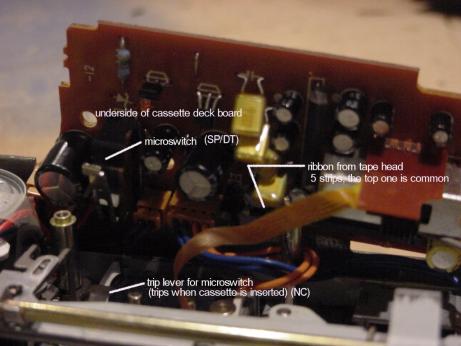
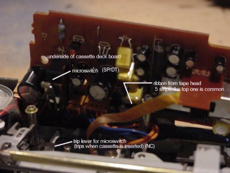
OK, Heres some pics. These are showing the cassette deck and underside of the board on it. The red (R) wire sends a signal or power to the deck and the radio. The red and white(R/W) wire returns a signal to the amp. On the microswitch, the R is on the (G) terminal. R/W is on the (NC) terminal. The R/W wire is connected to nothing else on the board or harness. When the switch is thrown, the R/W is disconnected, the radio quits, and power is sent to the deck thru the (NO) terminal. I spliced into the 3 remaining wires. I think that the brown(B) wire is a ground, and the orange(O) and white(W) are the left and right channel positives. Haven't figured out which is which. If I trip the switch manually,no tape inserted, it cuts the signal and allows music from the CD player to pass thru. But ONLY if I have the 100uF caps on the channels from the spliced in wires. Are you still following me?........ No caps and the signal is too much, and it wont play, it just thumps bad. And I get the hum. And some of the radio sound. With these caps the signal seems to be a tad too weak.

I'll mess with it some more and post back soon!

and no digital multimeter tonite, the weather here turned bad(St.Louis) so my buddy didn't come over with it........

Aux Input for an Older Delco Radio -- posted image.

Aux Input for an Older Delco Radio -- posted image.

mickstan_vr 
Member - Posts: 16
Member spacespace
Joined: November 27, 2006
Location: United States
Posted: November 30, 2006 at 7:38 PM / IP Logged  

WOW!!!! lets try that again..............

Aux Input for an Older Delco Radio -- posted image.

master5 
Silver - Posts: 1,123
Silver spacespace
Joined: October 10, 2006
Location: United States
Posted: November 30, 2006 at 10:55 PM / IP Logged  

when I stated "checking signal" I was refering to + and/or - voltage for switching in and out of tape mode..not audio. If you do not have access to an o-scope for signal you can do it "trial and error" method by hooking the unit to a test bench and sending an audio signal to random wires from the tape head that have previosly been verified as not having voltage or ground. The leftover wires must be audio as there is not that much to a tape head. You will hear audio when you are on the right wires.

master5 
Silver - Posts: 1,123
Silver spacespace
Joined: October 10, 2006
Location: United States
Posted: November 30, 2006 at 11:03 PM / IP Logged  
Also..in the picture you show an spdt switch..and a n/c switch. We can assume the n/c switch is opened when a cassstte is inserted..a no brainer..but what is happeneing with the spdt..once i know this I can guide you to the switching method you can use to perform this function without needing to insert a tape.
Page of 4

  Printable version Printable version Post ReplyPost New Topic
You cannot post new topics in this forum
You cannot reply to topics in this forum
You cannot delete your posts in this forum
You cannot edit your posts in this forum
You cannot create polls in this forum
You cannot vote in polls in this forum

  •  
Search the12volt.com
Follow the12volt.com Follow the12volt.com on Facebook
Saturday, April 20, 2024 • Copyright © 1999-2024 the12volt.com, All Rights Reserved Privacy Policy & Use of Cookies
Disclaimer: *All information on this site ( the12volt.com ) is provided "as is" without any warranty of any kind, either expressed or implied, including but not limited to fitness for a particular use. Any user assumes the entire risk as to the accuracy and use of this information. Please verify all wire colors and diagrams before applying any information.

Secured by Sectigo
the12volt.com spacer
Support the12volt.com
Top
the12volt.com spacer