the12volt.com spacer
icon

r/s bypass output w/ starting


Post ReplyPost New Topic
< Prev Topic Next Topic >
hinge817 
Member - Posts: 31
Member spacespace
Joined: January 12, 2005
Location: United States
Posted: March 05, 2007 at 3:15 PM / IP Logged  
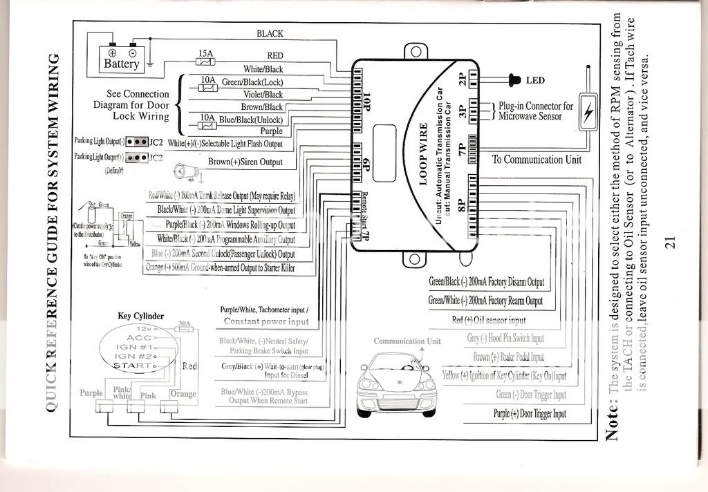
hey ppl, just trying to clarify things. i have a 2003 dodge ram 3.7 reg cab plain janer. no electric anything. i have added autoloc's basic 2 actuator kit. works good. im adding a AGA-1201 alarm with R/S. havent installed any alarm components yet although i do have the dash and such taken out for when i have more time. my question is about the "(-)200mA bypass output when romote start" blue/white wire. from what ive read i would just use this if i had additional sensors (glass, vibration, etc).  i have printed the color code guides and related info on my truck off here, very helpful. im sure ill have other questions but i think for now this is it. oh yeah, as far as the starter kill, should i use the wires on the ignition harness or find the power supply for the distributor. although my truck doesnt have one. it uses coil packs on each spark plug.ill try to get a diagram so you can see what im referring to. thanks
master5 
Silver - Posts: 1,123
Silver spacespace
Joined: October 10, 2006
Location: United States
Posted: March 05, 2007 at 3:37 PM / IP Logged  

The neg output bypass wire is typically used for bypassing factory immobilizers..although it could be used for bypassing sensors as well. However, most systems..especially newer ones..do this automatically.

As far as the starter kill just use the crank wire at the ignition harness..do not mess with the coil packs..although in some cases you can tap off a neg wire for tach sense..but that is safe as the tach sense wire is very high resistance so will have no adverse effects.

hinge817 
Member - Posts: 31
Member spacespace
Joined: January 12, 2005
Location: United States
Posted: March 05, 2007 at 4:14 PM / IP Logged  
alright, thanks. i was thinkin about using one of the coil packs as the tach signal. the alarm can also use oil light input as well. as far as the starter, your saying use the starter wire at the ignition harness. making a cut  and one side would be the car side and other key side, using the relay supplied with alarm as starter kill. i think thats how it works anyways.
master5 
Silver - Posts: 1,123
Silver spacespace
Joined: October 10, 2006
Location: United States
Posted: March 05, 2007 at 6:52 PM / IP Logged  

Yep..you got it..once you cut the crank wire you have 2 sides...key side (coming from the ignition switch)..and car side (I call it "motor" side). Wire it to the relay as per the directions and you have a simple starter kill.

As far as what you stated about the oil light..I have never heard of that..can you explain more about what the instructions state this does for the remote start. I would think the only valuble use for that would be to shut down the remote start if the oil pressure was to drop..I can't imagine the oil light to be a reliable substitute for tach sense or even voltage check for that matter.

hinge817 
Member - Posts: 31
Member spacespace
Joined: January 12, 2005
Location: United States
Posted: March 05, 2007 at 7:07 PM / IP Logged  

ok lets see. violet/white wire: Tach input or high-voltage sensing input wire... blah blah about where to find right connection....  . correct wire shows between 1V to 6V (AC) and fluctuates with the idle of the engine when testing with MM.  8-pin harness... pin 3: RED WIRE (+) connect to wire which is usually connected to the Oil Sensor on the dashboard or to the alternator in the engine compartment and connect this wire. 2-3 V on MM when key is turned to second turn position in the key cylinder and +12V - +14V shows when the starter is running.   seems a lil confusing to me as to where to hook it. let me know what ya think

master5 
Silver - Posts: 1,123
Silver spacespace
Joined: October 10, 2006
Location: United States
Posted: March 05, 2007 at 7:23 PM / IP Logged  

Ok..that is confusing...ignore all that stuff..the person who wrote that manual obviosly has too much free time on thier hands...basically they are clutching at straws to find a zillion possible ways to get a tach signal.

For your vehicle it is much simpler. Tap onto any wire at either the ignition coil...coil pack...or injectors that is NOT GREEN/ orange. Don't let that confuse you either..its about choice..simply choose a location that is easiest for you to get to..apparently you will see green w/ orange wire there...tap onto the other wire..program the tach as per the directions..and you are home free with that.

Hope this info helped.  

master5 
Silver - Posts: 1,123
Silver spacespace
Joined: October 10, 2006
Location: United States
Posted: March 05, 2007 at 7:36 PM / IP Logged  

I got curious and looked up that system online. It seems there are wires for the alternator and oil pressure light and I believe those are to sense for a high or low condition.perhaps an option if you can't get to a tach wire..the tach sense is designed to let the RS unit know when the engine is actually running..so it knows to re-start if it didn't start..as well as not over grind the starter or re-engage it once it is running by attempting to start the vehicle again when it is already running. That wire should also sense for RPM as well and shut down if high revs occur..but I can't say if that particular unit does it..I know nothing about that brand at all..never heard of it.

Now the voltage sense (which can be used to sense the engine running as well)..and perhaps this oil pressure sense can do the same..but the relaibilty of using the tach sense is fool proof and if using that I would not worry about the wires for the alternator and oil light.  Unless the instructions state that you MUST hook these up for safety...even if using the tach..then I would be more concerned.

hinge817 
Member - Posts: 31
Member spacespace
Joined: January 12, 2005
Location: United States
Posted: March 05, 2007 at 7:54 PM / IP Logged  

absolutely helpful, the book is kinda vague to begin with, seems like they give ya just enuf to cause headaches. ill get a diagram up and ask a few questions as well.

r/s  bypass output w/ starting -- posted image.

hinge817 
Member - Posts: 31
Member spacespace
Joined: January 12, 2005
Location: United States
Posted: March 05, 2007 at 7:57 PM / IP Logged  

https://i178.photobucket.com/albums/w247/monetxgirl/alarminstructions.jpg

Link to view image of alarm instructions.  Please excuse double post...

master5 
Silver - Posts: 1,123
Silver spacespace
Joined: October 10, 2006
Location: United States
Posted: March 05, 2007 at 9:09 PM / IP Logged  

OK...as I thought..it says clearly on the side of the instructions that if you are using the tach wire (and I already said where you can get that) you do not hook up the oil switch or alternator wires..so cool..just hook the tach wire and tape off the other 2.

There are several other wires you will not need to hook up for the remote start to work so it shouldn't be that bad. The neutral safty switch wire will need to be grounded if you choose not to hook it up...just remember on some chyslers that the neutral safety is before the crank wire so make sure never to remote start if the truck is in gear..which is unlikly if you keep the remote on your key chain. In other words to leave the vehicle and take the key out it has to be in park..so not really a major concern..just something they add for liability purposes.

There are a dozen other wires you will not need as well but when you have any questions just ask. And yes..that diagram is a clusterfu{k and a half...did you get that system on ebay or something?

Page of 2

  Printable version Printable version Post ReplyPost New Topic
You cannot post new topics in this forum
You cannot reply to topics in this forum
You cannot delete your posts in this forum
You cannot edit your posts in this forum
You cannot create polls in this forum
You cannot vote in polls in this forum

  •  
Search the12volt.com
Follow the12volt.com Follow the12volt.com on Facebook
Saturday, April 20, 2024 • Copyright © 1999-2024 the12volt.com, All Rights Reserved Privacy Policy & Use of Cookies
Disclaimer: *All information on this site ( the12volt.com ) is provided "as is" without any warranty of any kind, either expressed or implied, including but not limited to fitness for a particular use. Any user assumes the entire risk as to the accuracy and use of this information. Please verify all wire colors and diagrams before applying any information.

Secured by Sectigo
the12volt.com spacer
Support the12volt.com
Top
the12volt.com spacer