the12volt.com spacer
icon

reverse polarity with a twist.


Post ReplyPost New Topic
< Prev Topic Next Topic >
hyperryd 
Member - Posts: 28
Member spacespace
Joined: November 12, 2006
Location: United States
Posted: March 10, 2007 at 12:15 AM / IP Logged  
I kept trying diodes and relays on the signal wire not the supply wire.  I will try that .  I really like simple if it will work.  Thanks for the replies guys.  I will keep you posted.
hotwaterwizard 
Silver - Posts: 1,350
Silver spacespace
Joined: December 11, 2003
Location: California, United States
Posted: March 10, 2007 at 12:15 AM / IP Logged  

OOPS Here is the correct Diagram

reverse polarity with a twist. - Page 2 -- posted image.

John DeRosa (Hotwaterwizard)
Stockton California
When in doubt, try it out !
hyperryd 
Member - Posts: 28
Member spacespace
Joined: November 12, 2006
Location: United States
Posted: March 10, 2007 at 12:25 AM / IP Logged  

I guess we are all posting at the same time. 

1. The valves use a light coil basically like a relay to activate them so they are very sensative.

2. If I use the diode on the the signal wires the way pictured, they don't stop any signals from feeding back.   On the valve twp leg, the diode will stop posative feedback, but not negative feedback.  Or am I just looking at that wrong?

I'm pretty sure that was the first configuration I tried, but I have tried a lot.  I think the biggest problem is the relays and valve coils are so sensative that the minute feedback is setting everything off.

hotwaterwizard 
Silver - Posts: 1,350
Silver spacespace
Joined: December 11, 2003
Location: California, United States
Posted: March 10, 2007 at 12:29 AM / IP Logged  
I thought about that too so I posted another diagram. We were posting at the same time several times.
John DeRosa (Hotwaterwizard)
Stockton California
When in doubt, try it out !
dualsport 
Silver - Posts: 983
Silver spacespace
Joined: September 27, 2005
Location: United States
Posted: March 10, 2007 at 12:34 AM / IP Logged  
This is the equivalent circuit if only diodes are used-
reverse polarity with a twist. - Page 2 -- posted image.
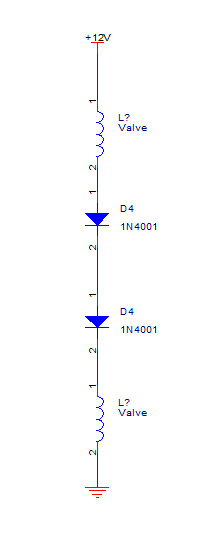
With the switch off, you have pretty much 1/2 the battery voltage across each of the valves, minus the bit of drop from the diodes. Relays generally have a lower turn off voltage than the turn on voltage, so that's probably why you noticed them staying on once they got energized.
Simplest might be to stick in another switch; nothing gets much simpler than a mechanical toggle switch.
hotwaterwizard 
Silver - Posts: 1,350
Silver spacespace
Joined: December 11, 2003
Location: California, United States
Posted: March 10, 2007 at 12:35 AM / IP Logged  
Ok lets find another solution
John DeRosa (Hotwaterwizard)
Stockton California
When in doubt, try it out !
dualsport 
Silver - Posts: 983
Silver spacespace
Joined: September 27, 2005
Location: United States
Posted: March 10, 2007 at 12:41 AM / IP Logged  
Adding a toggle switch is starting to look good now- reverse polarity with a twist. - Page 2 -- posted image.
Let's first make SURE the friend doesn't want to reconsider that option reverse polarity with a twist. - Page 2 -- posted image.
hyperryd 
Member - Posts: 28
Member spacespace
Joined: November 12, 2006
Location: United States
Posted: March 10, 2007 at 12:43 AM / IP Logged  

The extra switch issue is this.  This is a 1965 Cadillac with front and back air bag suspension.  My friend doesn't want a modern switchbox  in the car.  I found a 1965 Caddy power seat switch that matches the interior perfectly and fits in the ashtray like it came from the factory that way.  So this is the switch we are talking about so I can't really add another swich.  My general theory is if a switch puts out a signal there has to be a way to use that signal to activate a relay or coil of some sort.  This one is challenging because of both polaritie on one wire, but my favorite saying is "If it was easy, everybody would do it."  There has to be a way we just have to find it.  I really do appreciate people who like a challenge as much as I do. 

hyperryd 
Member - Posts: 28
Member spacespace
Joined: November 12, 2006
Location: United States
Posted: March 10, 2007 at 12:48 AM / IP Logged  
The other nice thing about the switch is there are two rockers switches to control the front and the rear that flank a joystick in the middle that will activate both switches up or down allowing him to control each end independantly with rocker or the whole car with the joystick.  It would be a sweet set up, I just have to make it work.
dualsport 
Silver - Posts: 983
Silver spacespace
Joined: September 27, 2005
Location: United States
Posted: March 10, 2007 at 12:52 AM / IP Logged  
It really does seem like there should be an exceedingly simple solution to it, doesn't it- there's not much to it.
McGyver could probably work it with chewing gum, duct tape, and a rusty nail- should be interesting if someone finds the way.
Page of 5

  Printable version Printable version Post ReplyPost New Topic
You cannot post new topics in this forum
You cannot reply to topics in this forum
You cannot delete your posts in this forum
You cannot edit your posts in this forum
You cannot create polls in this forum
You cannot vote in polls in this forum

  •  
Search the12volt.com
Follow the12volt.com Follow the12volt.com on Facebook
Friday, April 19, 2024 • Copyright © 1999-2024 the12volt.com, All Rights Reserved Privacy Policy & Use of Cookies
Disclaimer: *All information on this site ( the12volt.com ) is provided "as is" without any warranty of any kind, either expressed or implied, including but not limited to fitness for a particular use. Any user assumes the entire risk as to the accuracy and use of this information. Please verify all wire colors and diagrams before applying any information.

Secured by Sectigo
the12volt.com spacer
Support the12volt.com
Top
the12volt.com spacer