the12volt.com spacer
icon

viper 150 esp/xcrs 500m, 87 bronco


Post ReplyPost New Topic
< Prev Topic Next Topic >
slawson2000 
Member - Posts: 47
Member spacespace
Joined: March 11, 2007
Location: United States
Posted: March 12, 2007 at 10:57 AM / IP Logged  

There is a switch in the dash that works when the accessories are on or there is a key in the tailgate that works all the time.  I am thinking I could tie it in at the dash with the unit getting power from somewhere else.  How does the 530T operate?  Is it a momentary switch?  Timed? Load sensing?

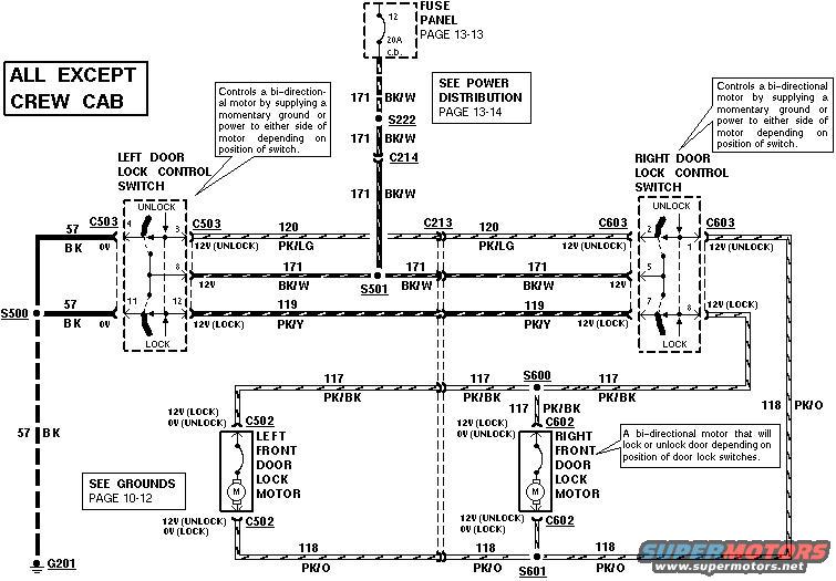
It just keeps getting better.  I am trying to figure out what type of door locks I have.  I thought I had it, but I guess not.  If I look at the factory schematics it looks like there is a ground loop that goes through the switches and motors while it is inactive.  Then when a switch is activated (unlock), the ground is broken in that spot and a 12+ is introduced going to the motor, back through the other switch (lock) which at rest is still grounded thereby completing the circuit.  I thought originally it was a type a, but it seems that it would just ground out.

I think it is a type c (reversing polarity).  From the ESP150 manual it looks like you loose the use of the factory switch when this is installed. - is that correct?  I'd like to double check before I dive into this side.  Here is a Ford factory diagram.

viper 150 esp/xcrs 500m, 87 bronco - Page 2 -- posted image.

Twelvoltz 
Platinum - Posts: 2,384
Platinum spaceThis member has made a donation to the12volt.com. Click here for more info.spaceThis member consistently provides reliable informationspace
Joined: March 24, 2005
Location: New Jersey, United States
Posted: March 12, 2007 at 2:12 PM / IP Logged  
Your truck is indeed a 5-wire for door lock control, if you take a look at the 5-wire diagram you can see that when the relays are not active and the wires you cut are connected via pins 87a and 30.
The 530T uses resistance to know when the motor has completed it's travel. Reading through the installation manual explains this on page 6.
Installer, IT support, and FFL. I need less hobbies.
slawson2000 
Member - Posts: 47
Member spacespace
Joined: March 11, 2007
Location: United States
Posted: March 12, 2007 at 2:37 PM / IP Logged  

Hmmm.  I think I got it.  So I need to pick up two relays to wire this in, I assume they should be rated for at least 30 amps each?

I have not picked up a 530T yet, it'll probably be a few months down the road.

slawson2000 
Member - Posts: 47
Member spacespace
Joined: March 11, 2007
Location: United States
Posted: June 24, 2007 at 2:48 PM / IP Logged  

Well, this is where I started.

https://www.the12volt.com/installbay/forum_posts.asp?tid=91560&KW=esp150

Now I am finally diving into the install tomorrow (Monday) and am hoping that a couple knowledgeable people will be around to help.  Any install suggestions would be helpful.  Drop the dash, don't drop the dash, etc.  Mostly I think I will need wiring advice or clarification. 

Thanks in advance.

slawson2000 
Member - Posts: 47
Member spacespace
Joined: March 11, 2007
Location: United States
Posted: June 24, 2007 at 6:06 PM / IP Logged  

So here begins the questions...

Ignition.  I am looking to see what ignition circuits need to be hooked up on the truck to make this work.  So far I am pretty sure I need to run:

xcrs Pink to vehicle RED / LT Grn - This should power up the charging circuits.

? xcrs Pink / White to vehicle WHITE/ lt blue - power to coil

?  I have no idea but I want the A/C/Heater circuit on truck - that is a must. Should I use the xcrs for that?  Does hooking up ESP150 H1/1 orange to xcrs orange work this relay?

? Cut the truck RED / lt blue starter circuit and the starter side goes to xcrs purple and the key side to xcrs green.

Thanks

slawson2000 
Member - Posts: 47
Member spacespace
Joined: March 11, 2007
Location: United States
Posted: June 25, 2007 at 2:45 PM / IP Logged  

Anyone?

So far so good.  The unit is fired up and the door locks, flashing lights, and horn works.  I think I want a soft chirp siren though.  Next comes the remote start....

Anyone?

slawson2000 
Member - Posts: 47
Member spacespace
Joined: March 11, 2007
Location: United States
Posted: June 26, 2007 at 11:36 AM / IP Logged  

Lets get a little more specific...

There is a BROWN / pink wire coming from the ignition switch that I guess is for the run output for the engine.  Does anyone know what this feeds?  Is it kooked up into the RED / lt green ignition wire somewhere down the road.  Do I need to hook this to Ing2 output of the xcrs?

JWorm 
Platinum - Posts: 2,208
Platinum spacespace
Joined: December 11, 2002
Location: New Hampshire, United States
Posted: June 26, 2007 at 12:41 PM / IP Logged  
Your post are very difficult to understand which is probably why nobody is responding to your thread. I'll give it a shot though.
I also understand you have a relay pack from a newer system and are trying to get it to work with a unit that used the older style relay pack.
Have you tested the BROWN / pink wire? Is it hot when:
the key is off?
the key is in the run position?
the starter is cranking?
That wire is not listed in the wiring diagram I have. If I remember correctly, it is an accessory wire that you don't need to connect.
slawson2000 wrote:

So here begins the questions...

Ignition.  I am looking to see what ignition circuits need to be hooked up on the truck to make this work.  So far I am pretty sure I need to run:

xcrs Pink to vehicle RED / LT Grn - This should power up the charging circuits.

Correct
slawson2000 wrote:

? xcrs Pink / White to vehicle WHITE/ lt blue - power to coil

I have no idea what you are trying to say above.
slawson2000 wrote:

?  I have no idea but I want the A/C/Heater circuit on truck - that is a must. Should I use the xcrs for that?  Does hooking up ESP150 H1/1 orange to xcrs orange work this relay?

The H1/1 orange wire has nothing to do with the accessory relay. Do you have the 5 wire harness that plugs into the remote start brain? It will have a red, yellow, pink, orange and purple wire. Also, do you have the 7 wire harness that plugs into the relay pack? It should have a red, pink, pink/white, orange, violet, ORANGE / black and blue wire.
slawson2000 wrote:

? Cut the truck RED / lt blue starter circuit and the starter side goes to xcrs purple and the key side to xcrs green.

At least you got that correct.
slawson2000 
Member - Posts: 47
Member spacespace
Joined: March 11, 2007
Location: United States
Posted: June 26, 2007 at 1:43 PM / IP Logged  

Sorry for the confusion...  just trying to get it done before I bake - it is supposed to be 108*+ today.

BROWN / pink is hot in the ignition/start position.  I figure it may be for the ignition accessories like the a/c.  I hooked it up to the XCRS pink/wht (ignition 2).  BROWN / pink is not in anything I have either, but is does come off the Ignition 2 spot on the ignition switch.  There are a couple Accessory spots on the ignition switch as well, but I am not doing those as I do not care if the radio and wipers work when no one is in it.

xcrs Pink to vehicle RED / LT Grn - got it thanks

xcrs Pink / White to vehicle WHITE/ lt blue - power to coil -  Never mind, it connects to the RED / lt grn down the harness.

I have the 5 wire harness and the 7 wire harness.  Currently i am wiring as you  indicated previously

5 pin harness       ----       7 pin harness

purple   ----       purple
orange ----       orange
pink      ----       pink AND pink/white
yellow   ----       yellow
red       ----        probably not needed...but may need to be hooked up to +12v - I a not hooking up at all.
Not needed        ----        blue
H1/1 orange       ----        ORANGE / black

Oh, and got the starter circuit together.

I have everything else in and am getting ready to try it out.  Am i ready?  Did I screw up or forget something?

Thanks for the help and patience.

JWorm 
Platinum - Posts: 2,208
Platinum spacespace
Joined: December 11, 2002
Location: New Hampshire, United States
Posted: June 26, 2007 at 3:10 PM / IP Logged  
Is there a thick grey / YELLOW in the ignition harness? That will probably need to be hooked up as well. It will have to do with the heat/AC.
What did you connect the BLACK/ white neutral safety input of the Viper to?
Everything else looks good.
Make sure you try to learn the tach signal before trying to remote start.
Page of 3

  Printable version Printable version Post ReplyPost New Topic
You cannot post new topics in this forum
You cannot reply to topics in this forum
You cannot delete your posts in this forum
You cannot edit your posts in this forum
You cannot create polls in this forum
You cannot vote in polls in this forum

  •  
Search the12volt.com
Follow the12volt.com Follow the12volt.com on Facebook
Friday, May 3, 2024 • Copyright © 1999-2024 the12volt.com, All Rights Reserved Privacy Policy & Use of Cookies
Disclaimer: *All information on this site ( the12volt.com ) is provided "as is" without any warranty of any kind, either expressed or implied, including but not limited to fitness for a particular use. Any user assumes the entire risk as to the accuracy and use of this information. Please verify all wire colors and diagrams before applying any information.

Secured by Sectigo
the12volt.com spacer
Support the12volt.com
Top
the12volt.com spacer