the12volt.com spacer
icon

turn signal, brake priority relay setup


Post ReplyPost New Topic
< Prev Topic Next Topic >
hotwaterwizard 
Silver - Posts: 1,350
Silver spacespace
Joined: December 11, 2003
Location: California, United States
Posted: June 09, 2007 at 6:46 PM / IP Logged  

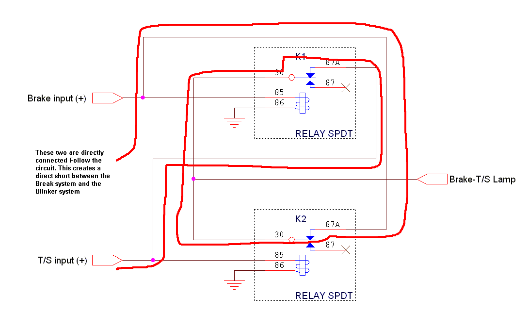
Show me in my diagram where the two circuits are connected. I can not see where they connect to each other. They are already Isolated as far as I can see.

The last one posted is a direct short between break and  Blinker system.

Keep it simple it makes less problems.

turn signal, brake priority relay setup - Page 2 -- posted image.

John DeRosa (Hotwaterwizard)
Stockton California
When in doubt, try it out !
hotwaterwizard 
Silver - Posts: 1,350
Silver spacespace
Joined: December 11, 2003
Location: California, United States
Posted: June 09, 2007 at 7:26 PM / IP Logged  

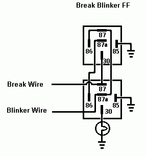
I bench tested mine and it works perfectly as designed.

It only latches if the Blinker signal does not flash.

Every time it flashes it latches and unlatches as it is designed to do.

turn signal, brake priority relay setup - Page 2 -- posted image.

John DeRosa (Hotwaterwizard)
Stockton California
When in doubt, try it out !
dualsport 
Silver - Posts: 983
Silver spacespace
Joined: September 27, 2005
Location: United States
Posted: June 09, 2007 at 11:34 PM / IP Logged  
hotwaterwizard wrote:

turn signal, brake priority relay setup - Page 2 -- posted image.

When you bench tested it, did you wire up both sides?
If the blinker is at 12V, you have 12V at terminal 87 of the top relay.
That's connected to the top relay's coil, so it gets energized.
When the relay is energized, 87 is connected to 30.
30 is connected to the bottom relay terminal 87, which is connected to your Break Wire input, which I'm assuming is connected to the other side also.
That ends up turning on the light on both sides, which makes it like a hazard light instead of a turn signal.
bwinkler 
Member - Posts: 8
Member spacespace
Joined: October 06, 2006
Location: United States
Posted: June 09, 2007 at 11:41 PM / IP Logged  

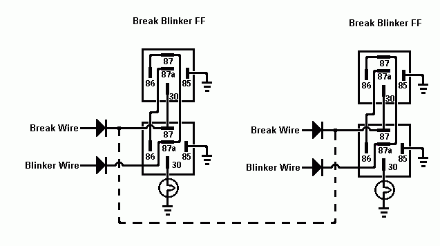
You're right about the direct short, this can be easily fixed though.  The circuit shown below,  +12V will break the continuity between the two sources in a normal case.  I tested this circuit on my bread board and it worked like it should for one side.  To keep it safe from stray voltages bleeding to the other side, a diode inline at each 30 pin output would clean the problem. 

hotwaterwizard wrote:

Show me in my diagram where the two circuits are connected. I can not see where they connect to each other. They are already Isolated as far as I can see.

turn signal, brake priority relay setup - Page 2 -- posted image.

________________
Brian D. Winkler
dualsport 
Silver - Posts: 983
Silver spacespace
Joined: September 27, 2005
Location: United States
Posted: June 09, 2007 at 11:44 PM / IP Logged  
hotwaterwizard wrote:

Show me in my diagram where the two circuits are connected. I can not see where they connect to each other. They are already Isolated as far as I can see.

The last one posted is a direct short between break and Blinker system.

Keep it simple it makes less problems.

turn signal, brake priority relay setup - Page 2 -- posted image.

Don't forget the path connections involves relays.
It's shorted only when both inputs are off, so it doesn't matter, zero volta on both inputs.
When *either* one goes active high, the relay turns on, and the connection you outlined is no longer present- it's actually a pretty simple setup.
Think of it like a XOR (exclusive OR) circuit: when one is high and the other is low, the output is high. When both are high or both are low, the output is low. It should be exactly the behavior needed for this application.
dualsport 
Silver - Posts: 983
Silver spacespace
Joined: September 27, 2005
Location: United States
Posted: June 10, 2007 at 12:11 AM / IP Logged  
bwinkler wrote:

To keep it safe from stray voltages bleeding to the other side, a diode inline at each 30 pin output would clean the problem.

It's simply not a problem amd unnecessary, but if you're really worried about two zero volt signals being connected together and really want to use a diode, you'll need to use a high current capable diode.
Keep in mind the path isn't simply relay coil current but power to the bulbs, which will need relatively high current.
All it would do is add another possible point of failure and waste power by dropping voltage unnecessarily. Don't do it- keep it simple.
hotwaterwizard 
Silver - Posts: 1,350
Silver spacespace
Joined: December 11, 2003
Location: California, United States
Posted: June 10, 2007 at 1:19 PM / IP Logged  

The blinkers are seperate and only one side will blink when it's corrosponding blinker is activated. The blinkers are isolated from one another. how can they trigger both sides when isolated.

John DeRosa (Hotwaterwizard)
Stockton California
When in doubt, try it out !
dualsport 
Silver - Posts: 983
Silver spacespace
Joined: September 27, 2005
Location: United States
Posted: June 10, 2007 at 9:54 PM / IP Logged  
Well, there should be a single brake line wire going to both the left and right sides, unless the brake switch is a double pole type.
When the blinker signal sends power backwards to the brake wire as I described earlier, it would turn on the other side at the same time. You can wiring up the second side in your bench test to confirm this, I haven't tried it; I'm only basing it on the diagram.
hotwaterwizard 
Silver - Posts: 1,350
Silver spacespace
Joined: December 11, 2003
Location: California, United States
Posted: June 11, 2007 at 9:27 PM / IP Logged  

After taking a second look at it I see what you are talking about. It works but I think a couple of Diodes would resolve the problem. The Diodes need to be heavy duty enough to handle the Bulb current .

However it will not fix the crow that I am eating now.

turn signal, brake priority relay setup - Page 2 -- posted image.

John DeRosa (Hotwaterwizard)
Stockton California
When in doubt, try it out !
dualsport 
Silver - Posts: 983
Silver spacespace
Joined: September 27, 2005
Location: United States
Posted: June 12, 2007 at 9:47 PM / IP Logged  
That looks good; all it needed was a bit of a tweak, and just adding a couple diodes at the brake wire inputs would do the job. Probably don't need the ones at the Blinker Wire inputs, so you can do it with just the two. Replacing the dotted line connection with the diodes is all it needed.
Lots of ways to skin a cat; that's what makes things interesting. Beats doing crossword puzzles.. turn signal, brake priority relay setup - Page 2 -- posted image.
Page of 5

  Printable version Printable version Post ReplyPost New Topic
You cannot post new topics in this forum
You cannot reply to topics in this forum
You cannot delete your posts in this forum
You cannot edit your posts in this forum
You cannot create polls in this forum
You cannot vote in polls in this forum

  •  
Search the12volt.com
Follow the12volt.com Follow the12volt.com on Facebook
Monday, May 5, 2025 • Copyright © 1999-2025 the12volt.com, All Rights Reserved Privacy Policy & Use of Cookies
Disclaimer: *All information on this site ( the12volt.com ) is provided "as is" without any warranty of any kind, either expressed or implied, including but not limited to fitness for a particular use. Any user assumes the entire risk as to the accuracy and use of this information. Please verify all wire colors and diagrams before applying any information.

Secured by Sectigo
the12volt.com spacer
Support the12volt.com
Top
the12volt.com spacer