the12volt.com spacer
icon

turn signal, brake priority relay setup


Post ReplyPost New Topic
< Prev Topic Next Topic >
hotwaterwizard 
Silver - Posts: 1,350
Silver spacespace
Joined: December 11, 2003
Location: California, United States
Posted: June 13, 2007 at 7:34 AM / IP Logged  
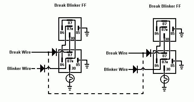
The dotted line is suppose to represent the internal break wiring in the car.
John DeRosa (Hotwaterwizard)
Stockton California
When in doubt, try it out !
dualsport 
Silver - Posts: 983
Silver spacespace
Joined: September 27, 2005
Location: United States
Posted: June 13, 2007 at 8:14 AM / IP Logged  
If that's the connection between the two sides, then it should be on the other side of the diodes or else one side would still feed the other when the T/S is on-
hotwaterwizard 
Silver - Posts: 1,350
Silver spacespace
Joined: December 11, 2003
Location: California, United States
Posted: June 13, 2007 at 8:33 AM / IP Logged  
turn signal, brake priority relay setup - Page 3 -- posted image.
John DeRosa (Hotwaterwizard)
Stockton California
When in doubt, try it out !
bwinkler 
Member - Posts: 8
Member spacespace
Joined: October 06, 2006
Location: United States
Posted: June 16, 2007 at 11:38 PM / IP Logged  

Gentlemen,

Hotwaterwizard: I was not able to get the circuit you described to work the first time without the diodes.  I was just on vacation so I've been out of touch for the last week.  I will try using the diodes just to play. 

Dualsport: The XOR type circuit works great.  You're right, it really doesn't need diodes.  When voltage is present, the relay will react to keep discontinuity. 

I find this trial a sucess.  It is great this info can be available for folks to build for themselves, get to know (maybe) electricity a little better and appreciate what its worth.  This simple circuit can be bought in a camper/trailer type store, but the deal was like $30+ dollars.  Through the use partsexpress.com, I was able to get all the necessary pieces for less and build it myself.  I also get to know my car a little better, too.

________________
Brian D. Winkler
bwinkler 
Member - Posts: 8
Member spacespace
Joined: October 06, 2006
Location: United States
Posted: June 24, 2007 at 10:25 PM / IP Logged  

dualsport wrote:
Here's a modification that should isolate the two inputs and allow the one side to blink when the brakes are on- basically just turns off the lamp whenever both the brake and T/S are on at the same time, but passes it through normally when only one is on at a time.

I have decided to use the circuit described by Dual Sport.  I was able to put the circuit together and try it out on the van.  The circuit works just like it is supposed to.  However, I found out that when brake and turn signal are on simulataneously, the flash rate of Blinker is too fast.  This makes sense because the T/S (Turn Signal) input only operates the coil of the relay for brake input.  During this condition and only this condition, the T/S flasher up front reads this as load missing at the rear, the relay coil impedance must be very small. 

To defeat this, I figure putting a resistor in the circuit matching the rating of the bulb.  The bulb is rated 27 Watts, at full voltage (14V).  The resistor to match the 27 watt rating would have to be fairly large according to some website data.  I put some thought into, the T/S is not on continuously but in a flash condition.  My question is, could I get away with a lower wattage resistor (say 10W?) knowing the load will not be continuous?  Without getting into too in dept with the flash rate, amount of time the resistor will sees load off and on yield a value suitably less than the bulb specification.

Any thoughts?

________________
Brian D. Winkler
dualsport 
Silver - Posts: 983
Silver spacespace
Joined: September 27, 2005
Location: United States
Posted: June 24, 2007 at 11:25 PM / IP Logged  
You might try getting an electronic flasher if you're currently using a standard version. They're designed with electronic circuits to make and break the circuit, and less sensitive to the load. They're commonly used when lamps are replaced with LEDs, which draw very little current compared to the original lamps. EP-26
You really want to avoid adding load resistors because they'll get pretty hot. Hot glue guns and soldering irons are about 20W, and you can see how hot they get. If you really have to do it that way, you might just wire in a bulb with sufficient wattage instead of resistors, by dissipating some of that energy as light rather than pure heat, it'd be cooler.
bwinkler 
Member - Posts: 8
Member spacespace
Joined: October 06, 2006
Location: United States
Posted: June 26, 2007 at 6:48 AM / IP Logged  

dualsport wrote:
You might try getting an electronic flasher if you're currently using a standard version. They're designed with electronic circuits to make and break the circuit, and less sensitive to the load. They're commonly used when lamps are replaced with LEDs, which draw very little current compared to the original lamps. EP-26 .

The only problem with that method is that this vehicle has onboard control modules.  I was not able to find a flasher box anywhere.  Then I reviewed the repair manual it does not list a flasher relay but an integrated control module, ICM or sometimes called the BCM.  The way this van was designed rules out option 1.

dualsport wrote:
You really want to avoid adding load resistors because they'll get pretty hot. Hot glue guns and soldering irons are about 20W, and you can see how hot they get. If you really have to do it that way, you might just wire in a bulb with sufficient wattage instead of resistors, by dissipating some of that energy as light rather than pure heat, it'd be cooler.

Do you really think it will get that hot with the on and off operation?  If the resistor were to be powered on continously, then yes with no doubt fear of the heat issue.  It has been on my mind, too,  just to wire the same lamp in place of the resistor.  The same lamp held in my hand with cloth on the glass does not get hot while flashing....

________________
Brian D. Winkler
hotwaterwizard 
Silver - Posts: 1,350
Silver spacespace
Joined: December 11, 2003
Location: California, United States
Posted: June 26, 2007 at 7:42 AM / IP Logged  

Spent hours figuring mine out.

No thank you just negitive remarks.

John DeRosa (Hotwaterwizard)
Stockton California
When in doubt, try it out !
bwinkler 
Member - Posts: 8
Member spacespace
Joined: October 06, 2006
Location: United States
Posted: June 26, 2007 at 8:45 AM / IP Logged  
hotwaterwizard wrote:

Spent hours figuring mine out.

No thank you just negitive remarks.

hotwaterwizard:

I do not know of any negative remarks by me.  And I mean to the nature of hurting your feelings.  I was not able to get the circuit you illustrated to work on my bread board and stated my findings.  In no way shape or form am I questioning your ability to create and invent circuits for different applications.  I thank you for your efforts, I spent several hours testing this stuff as well.  Sorry for the delay.

________________
Brian D. Winkler
hotwaterwizard 
Silver - Posts: 1,350
Silver spacespace
Joined: December 11, 2003
Location: California, United States
Posted: June 26, 2007 at 8:48 AM / IP Logged  

I figured out that I shouldn't post anything before I drink my morning Coffee.

Sorry not quite awake yet.

John DeRosa (Hotwaterwizard)
Stockton California
When in doubt, try it out !
Page of 5

  Printable version Printable version Post ReplyPost New Topic
You cannot post new topics in this forum
You cannot reply to topics in this forum
You cannot delete your posts in this forum
You cannot edit your posts in this forum
You cannot create polls in this forum
You cannot vote in polls in this forum

  •  
Search the12volt.com
Follow the12volt.com Follow the12volt.com on Facebook
Monday, May 5, 2025 • Copyright © 1999-2025 the12volt.com, All Rights Reserved Privacy Policy & Use of Cookies
Disclaimer: *All information on this site ( the12volt.com ) is provided "as is" without any warranty of any kind, either expressed or implied, including but not limited to fitness for a particular use. Any user assumes the entire risk as to the accuracy and use of this information. Please verify all wire colors and diagrams before applying any information.

Secured by Sectigo
the12volt.com spacer
Support the12volt.com
Top
the12volt.com spacer