the12volt.com spacer
icon

basic l.e.d. wiring


Post ReplyPost New Topic
< Prev Topic Next Topic >
corrollaman 
Member - Posts: 38
Member spaceThis member has made a donation to the12volt.com. Click here for more info.spacespace
Joined: November 17, 2009
Location: Kansas, United States
Posted: July 15, 2012 at 3:38 PM / IP Logged  

basic l.e.d. wiring -- posted image.

I know I read that you solder negative to positive when doing an array, but this is backwards to what I am seeing on the internet.

Thought I would throw this by the experts for a sanity check.  What worked for me also has the correct voltage.  I have a power supply with 12V output and when I measure the L.E.D power it is at 2V. 

Is what I am doing correct.  Everything I show makes me think I am just not seeing it correctly .... SANITY CHECK PLEASE!!!  Thanks guys/gals

ajm
oldspark 
Gold - Posts: 4,913
Gold spacespace
Joined: November 03, 2008
Location: Australia
Posted: July 15, 2012 at 7:42 PM / IP Logged  
You have mistaken the LED polarity. The circuit will not work as drawn the 2nd way.
How do you know you have the line-end towards +ve?
And where the resistor sits is no issue. It merely has to be anywhere in series with the LED.
corrollaman 
Member - Posts: 38
Member spaceThis member has made a donation to the12volt.com. Click here for more info.spacespace
Joined: November 17, 2009
Location: Kansas, United States
Posted: July 17, 2012 at 7:45 AM / IP Logged  

Backward-biased diode.

I thought I was just loosing it, as I stated before.. but I looked over the LED several times.. Negative being the flat side of the LED, Negative being the larger part of the LED... etc..

I then ran across an article that described my setup. http://download.micron.com/pdf/education/lessonplans/electronic_components.pdf

Out of all the youtube videos, and articles I have read trying to understand my predicament, this is the only thing I could find that would explain what I was running into. This then lead me to transistors... Which raised more questions..

So, what would you say about that? (Not being argumentative, just trying to understand 100%)  I go big or not at all.. so if i can't understand something.. ie.. this project.. I wont finish it..

ajm
oldspark 
Gold - Posts: 4,913
Gold spacespace
Joined: November 03, 2008
Location: Australia
Posted: July 17, 2012 at 10:12 AM / IP Logged  
Just a prelim reply...
That's a good reference link.
My condolences - you may be headed down the path of electronics. (Welcome! But commiserations. But then lots of enjoyment.)
And I'd have to check, but the "big element" looking thru the LED being -ve sounds correct. (I can never remember the flat side nor short-lead or square-lead convention.)
But the LED should not work if it is reverse biased.
Having said that, I will not rule out incorrectly marked components.
Though I doubt the "big" being -ve would be incorrect (it's such an automated and exact construction process), I won't discount it.
The most likely is wiring confusion followed by incorrect supply polarity. (I have had the pleasure of seeing a car battery whose case-embossed + & - legend was wrong! So too the terminal sizes since -ve & +ve leads/terminals hooked up normally to the "incorrect" polarities!)
Alas I'm about to hit the sack & am too tired.
I'll get back to you later (kick me if I forget) and take on your "argumentative" stance. (That's a joke. You are not being argumentative. You are reporting your observations. I expect it to be some simple "D'oh" experience. But I thought the same when my mate reported sparks from his correctly connected battery, but it turned out he had the one in a thousand or million situation of an incorrectly labelled mass produced common car battery. And I'd love to see a "reverse constructed" LED!)
BTW - if you do find a d'oh and great embarrassment, please report ASAP. (I've been there, done that.) Until then, IMO you are right until proven wrong. But we'll do a few checks... later.
corrollaman 
Member - Posts: 38
Member spaceThis member has made a donation to the12volt.com. Click here for more info.spacespace
Joined: November 17, 2009
Location: Kansas, United States
Posted: July 17, 2012 at 6:57 PM / IP Logged  

I was pretty tired when it was all said and done.. I am traveling right now so I am just researching and doing a lot of reading to prepare for exactly how i want this project to go, how complicated to make it.. or not make it.. and understand it completely so I can do it again or tell a few friends how i made it happen.

I will remind you this weekend when I am actually hands on again and then i can take pics and post them of how backwards it is.. or isnt.. Thanks for the help.. Electronics are awesome.. Never really had a reason to play with all this stuff, but my corrolla project got me started and the passions flowing..

ajm
corrollaman 
Member - Posts: 38
Member spaceThis member has made a donation to the12volt.com. Click here for more info.spacespace
Joined: November 17, 2009
Location: Kansas, United States
Posted: July 21, 2012 at 1:34 PM / IP Logged  

Okay.. made it back in one piece...

Okay.. LED's are essentially Diodes(one way check valves).. So how can you connect them in a Series... positive to negative, negative to positive.. Electricity only flows in one direction through diodes(leds)..

So I hooked up 8 LEDs in what I believe to be parrallel.. .negative to negative, pos to pos.. with a resistor in the circuit..

I dont know how all these people on the internet are able to wire them in a series.. im thinking they are meaning a series to be in a row.. but not the technical aspect of the leads going pos to neg.. neg to pos.. I have included some pics..

basic l.e.d. wiring -- posted image.

basic l.e.d. wiring -- posted image.     

ajm
oldspark 
Gold - Posts: 4,913
Gold spacespace
Joined: November 03, 2008
Location: Australia
Posted: July 21, 2012 at 7:45 PM / IP Logged  
Oh Man, you're going to kick yourself after the next few lines... (of text, not recreational powders!)
But first I'd like to repeat "welcome to electronics" (and maybe stress my aforementioned condolences {LOL}), AND add that I was impressed by your work above - including that "101" link.
In fact, no, maybe I won't tell you. You were tired, and then away. That's a rude interruption to your thinking processes yadda yadda... (That's right isn't it?)
Two ways I can tackle it...
The first is coupled with a diode & LED circuit and wiring trick.
The diode symbol is a line and arrow like --->|---
So what?
Well, that symbol has it all...
The arrow points in the direction of the current flow.
[ +ve to -ve, ie (+) +ve ---->|--- -ve (-) so current here flows left to right thru the diode. ]
The other main thing is that it's (vertical or perpendicular) line is the BAND on the diode body, hence the diode's "band" end points to the more -ve voltage if you want it to conduct. (They can be mounted "back to front" for voltage limiting or spike suppression. Forget that for now, but later maybe look at the spike suppression diode placed across relay coils (86 & 85). I/we might discuss that later.)
A trivial thing from the diode "arrow & band" symbol is that ruddy Anode (+ve) and Cathode (-ve) jargon. (I couldn't even remember which meant +ve (anode) or -ve until, perhaps(!?), recently.)
The lile end is a "K" - ie, ---|<--- = ---K--- to that's the Kathode = Cathode end.
Ergo, the other end is the anode, but that's confirmed by the arrow head > which is a sideways A.
Well that's how I remember it. And that's how I could tell people that the anode is the +ve end - ie, working backwards, I knew current traveled +ve to -ve thru the diode hence into the arrow and out of the line/band, +ve so into the arrow = A hence +ve is the anode.
A pause or digression here. Part way thru the above text I thought here I go again - a long reply for a potential one line (7 word) simple answer. And that was before the last block about how I determine +ve = Anode!
But I'm in my typical "101" ramble teaching mode - even though many could figure most out from a simple answer.
Okay, so applying the above to LEDs.
As you said, LED is merely a diode, but it emits light. Hence the LED symbol is a diode with a couple of squiggle-arrows off it to symbolise the emission of photons/light.
[ FYI - voltage-drop = "forward voltage drop" ramble:... IE - optional; skip this for later...
Of course diodes have a forward voltage drop and that drop depends on the type of diode or color of LED, as well as the amount of current thru it.
Common silicon diodes typically have a 0.6 - 0.7V forward voltage drop whilst older germanium types were ~0.2V. New "fast" Schottky diodes are ~0.3V. (As to the current effect, a high-current silicon diode's voltage drop may be 0.6V at low current, and over 1.0V at high current (eg, 100A).)
LEDs vary from typical reds with ~1.7V to whites with ~3.4V.   
BTW - the reverse blocking voltage should be infinity - ie, NOT let "reverse" current thru no matter what the voltage is - but in practice there is a "reverse breakdown voltage" which does simple means the reverse voltage at which the diode will break down (ie, conduct, or self-destruct, etc). LEDs may have low reverse breakdown voltages (hence they may need a normal diode in series for AC power etc), but silicon diodes are usually 50V upwards. For 12V automotive systems 50V diodes (eg, 1N4001) should be fine, but usually the more common 1N4004 with 400V PIV (Peak Inverse Voltage) is used. The 1N4 series has a 1A rating (max forward current) and the last digits designate their PIV (but with no direct numerical relationship other than increasing, eg, 1N4001, 1N4002, 1N4004, 1N4007 have 50V, 100V, 400V & 1,000V max reverse voltages (PIVs) respectively. The missing numbers are other voltages that are no longer produced, but essentially the 1N4004 (400V) & 1N4007 (1kV) are the only two still in common production and supply. The 400V 1N4004 rating is better suited to automotive 12V systems anyway since a vehicle can have high-voltage spikes of 200V etc.     
/end vd ramble ]
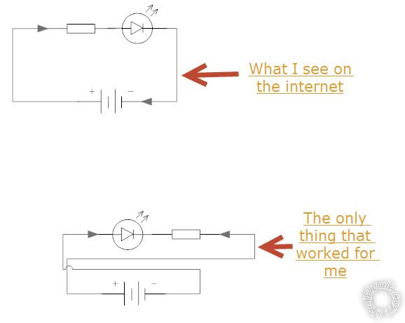
Anyhow, back to your problem of LEDs in series.
Draw a few diode symbols in series.
Now think how could you connect them so that they all pass current in the same direction? IE - which way do the arrows point? Then compare that to what you wrote in the first line of your last reply...
Kicking yourself yet?
You had the answer - a diode "the wrong way around" blocks the current. (Or as I say, it hits a brick wall - ie, the line or band.)
[ More optional ramble
Incidentally (again!), you may know that the current thru all series components is the same (it has to be - where else can the current go?). And (therefore or hence...) the sum (total) of all the voltages across each component adds up to equal the supply voltage.
Hence your resistor should still carry (say) 20mA but at a lower voltage when there is more than one LED in series (not parallel!!).
That means a lower resistor, but the single LED's resistor should still work fine. (LED dimness is NOT proportional to the resistance. But that's another topic. Put is this way, LEDs are NOT amongst the first things to be taught in electronics though they may be covered early on because they are great to use in circuits, but few understand LED characteristics. In fact I still have colorful discussions regarding LEDs - usually along the lines of how critical there AREN'T wrt to voltage, and to an extent, current.
/end ramble ]
Maybe I should have started with the second way I could tackle your problem, but it might be a spoiler if you haven't kicked yourself yet...
Think about how other "polar" devices are connected, eg:...
How do you align batteries in torches and remotes etc?
How do series magnets align themselves?
BTW - I haven't gotten further on your possible "faulty" LED. I've bee meaning to search for instances of backward constructed LEDs - like the car battery I mentioned with incorrectly molded + & - terminal labels.
Though maybe the LED's flat side could be misaligned (IMO still doubtful though), I consider it almost impossible to invert the internal connections to the electrodes (terminals/wires) - ie, the Kathode/-ve should always be to the bigger "flag" electrode (as usually seen looking thru the LED from the side).
Isn't it nice starting off a Sunday with a nice relaxing read?
Till next.... (Sunday?)
Good luck.
corrollaman 
Member - Posts: 38
Member spaceThis member has made a donation to the12volt.com. Click here for more info.spacespace
Joined: November 17, 2009
Location: Kansas, United States
Posted: July 22, 2012 at 10:14 PM / IP Logged  

Recreational powders... what is that.. hehe I have no idea what your talking about.. <G>

Yes, I was totally kicking myself.  I was sooooo relieved to know I was just understanding it wrong.. I guess I had just assumed I knew enough..

Thank You so much for the explanation... I knew enough to be confused... lol.. the Radioshack guy directed me toward the internet and that didnt answer my question... so he pulled the busy card and would call me back.. lol..  This is of course after I went in with my breadboard all wired up and he took pictures.. hehe 

Now that I know what im dealing with and have successfully setup the series/parallel up .. So next is figuring out how to calculate the resistors.  2 resistors.. one for the running tail light and one for the brake.. figuring out the best contrast without blinding the people behind me.basic l.e.d. wiring -- posted image.

I will start a new thread for that.

Thanks again

ajm
oldspark 
Gold - Posts: 4,913
Gold spacespace
Joined: November 03, 2008
Location: Australia
Posted: July 22, 2012 at 11:25 PM / IP Logged  
I'm so glad you kicked yourself. That sounds promising.
"I knew enough to be confused... lol." Oh yeah - I know that one!
With the resistor calcs, the first to get is the one for max brightness (brakes).
You then ADD another series resistor to get the required taillight dimness.
The final circuit is with (say) the added dim resistor from +12V to the "max brightness" resistor to the LED+ (with LED- to GND).
An SPST relay is then connected with 30 to +12V and 87 to the junction of the 2 resistors with the relay coil actuated by the brake switch (eg, 86 from the switched +12V and 85 to GND).
When the brake is applied, the relay bypasses (or shorts out) the "dim" resistor leaving only the "bright" resistor in series, hence full brightness.
There are other methods too.
And if you have parallel strings, you'll have to decide if a single dim and single bright resistor is acceptable.
Ideally each string should have its own resistors, but that makes the dim bypassing difficult though each string could have its own "bright" resistor and a single dim resistor to feed the lot. That way, if strings fail, the rest can be no brighter than "bright" and they won't blow.
If that's not understood, consider a few LED strings supplied through a single resistor. That resistor might limit the LED currents to 20mA.   But if one string is lost, it means more than 20mA to the remainder. Etc etc.
Single resistors for multiple strings are often used where there are MANY strings eg, 10 or more so that loss of one string increases current by only ~10%, 2 strings ~20% etc.
If only a few strings - say 2 or 4 - then one string loss can mean a doubling or extra ~30% for the remaining strings, and that could be enough to severely effect LED life.
Mind you, the above are subjective and determined by string or LED loss probability (ie, statistics). LEDs are supposed to last forever in theory, but then there is the wiring, fatigue etc.
Usually multiple strings are PWMd (Pulse Width Modulated) whereby the Duty Cycle of the PWM determines the brightness. That can be done with a single "bright" resistor for each string (to protect the string) and then the PWM is set for (say) 30% for taillights and switched to 100% (or 99% etc) for bright.
Resistors can even be omitted when the PWM is instead set for (say) 20% (dim) and a max of 80% (bright) assuming 80% is the max duty cycle tolerated by the LEDs without any current limiting series resistor.
PWM also has the advantage that brightness can be altered without the need to change resistors.
PWM is another topic. I'll put that under "Avalanche Theory" as in one electronic issue avalanches into a plethora of other headaches techniques - not to be confused with Semiconductor Avalanche Theory or Mode etc.
corrollaman 
Member - Posts: 38
Member spaceThis member has made a donation to the12volt.com. Click here for more info.spacespace
Joined: November 17, 2009
Location: Kansas, United States
Posted: July 23, 2012 at 2:35 PM / IP Logged  
I want to do what is best.. but am wondering what the Cons or Pros are of doing it this way below.. (taken from another project i found on the internet)
basic l.e.d. wiring -- posted image.
ajm
Page of 5

  Printable version Printable version Post ReplyPost New Topic
You cannot post new topics in this forum
You cannot reply to topics in this forum
You cannot delete your posts in this forum
You cannot edit your posts in this forum
You cannot create polls in this forum
You cannot vote in polls in this forum

  •  
Search the12volt.com
Follow the12volt.com Follow the12volt.com on Facebook
Tuesday, April 23, 2024 • Copyright © 1999-2024 the12volt.com, All Rights Reserved Privacy Policy & Use of Cookies
Disclaimer: *All information on this site ( the12volt.com ) is provided "as is" without any warranty of any kind, either expressed or implied, including but not limited to fitness for a particular use. Any user assumes the entire risk as to the accuracy and use of this information. Please verify all wire colors and diagrams before applying any information.

Secured by Sectigo
the12volt.com spacer
Support the12volt.com
Top
the12volt.com spacer