the12volt.com spacer
icon

remote start, 2004 grand prix


Post ReplyPost New Topic
< Prev Topic Next Topic >
amsanders843 
Member - Posts: 8
Member spacespace
Joined: November 17, 2011
Location: South Carolina, United States
Posted: November 22, 2011 at 2:08 PM / IP Logged  
Good evening, I just finished installing my remote start/alarm system in my 2004 grand prix. I used the bmw nitro 433 system with the 556U bypass module. EVERYTHING works fine except for remote starting the car. The alarm, door locks, trunk pop, etc all work accordingly. When I try to RS the car, I hear the bypass module clicking, nothing happens, and the whole system stops working. Then I have to unhook my neg batt cable n rehook it to get it workin again. I have the starter kill (n/c prewired relay) wired that 85 GWR, 86 ign12V, 30 starter side, 87a key side. Ive tested all of my wires, all carry the charge they're suppose to, to and from the system. Id really appreciate it if someone would help. I know the rs system isn't a usually used one such as viper, but that shouldn't b an issue. I can provide pics, etc to assist!!
howie ll 
Pot Metal - Posts: 16,466
Pot Metal spacespace
Joined: January 09, 2007
Location: United Kingdom
Posted: November 22, 2011 at 4:49 PM / IP Logged  
Sorry but I know nothing about either the car or the R/S except that 85 on that relay should be GWA* not GWR, the GWR should go to the by-pass blue wire.
*GWA = Ground whilst armed, GWR = Ground whilst running A.K.A. status output.
kreg357 
Platinum - Posts: 7,827
Platinum spaceThis member has made a donation to the12volt.com. Click here for more info.spaceThis member has been recognized as an authority in Electrical Theory. Click here for more info.spaceThis member has been recognized as an authority in Mobile Security and Convenience. Click here for more info.spacespace
Joined: January 30, 2009
Location: Pennsylvania, United States
Posted: November 22, 2011 at 7:00 PM / IP Logged  

Your wiring on that external relay looks like Anti-Grind not Starter Kill. 

Being as you cut the Starter wire and inserted the relay, it now matters where you

connect the BMW 433 Violet Starter Output wire.  It should be either to Pin 87 or
on the Pin 30 side of the cut starter wire.

      Grand Prix                                                                                                        BMX 433  Thick IGN wires

12volts          red (50A)  +        back of fuse box, passenger dash
Starter           yellow  +             ignition harness                                               Purple 
Ignition          pink  +                ignition harness                                                Pink
Accessory     brown  +            ignition harness                                               Orange
 
The BMW 433 Blue/White wire should go to the 556UW Blue (-) Status Input.  If you
connect the Blue/White wire to more than one place, diode isolate the connections.

Soldering is fun!
amsanders843 
Member - Posts: 8
Member spacespace
Joined: November 17, 2011
Location: South Carolina, United States
Posted: November 23, 2011 at 5:06 PM / IP Logged  

I switched the 30pin to the key side and 87a to starter side. connected the purple starter wire to the starter side 87a; 86 ign 12V, 85 GWA wire from r/s..these are all of my connections

BMW---->Car

purple wire----starter side pin 87a
orange wire----brown acc wire ign switch
red wire----WHITE/ black constant 12V ign switch
pink wire----pink ign wire ign switch
pink/white wire----pink ign wire BCM
PURPLE / white wire----tach wire at PCM, confirmed tach reading
BLACK/ white wire----park break switch wire BCM
blue/white wire----blue wire 556U

GREEN/ black wire----purple fac disarm wire

GREEN / WHITE wire----lt green fac arm wire
brown wire----white brake wire
yellow wire----(2nd)pink ign wire BCM
green wire----diode isolated door trigger wires BCM

orange wire----87a starterkill/antigrind relay

blue wire----blue pssnger unlock wire
BLACK/ white wire----tapped into green door trig wire on r/s
WHITE/ black wire----relayed to trunk release wire

brown wire---red siren wire

white wire----parking lights wire
door wires--driver door lock/unlock wires
all power wires were connected, all ground wires were properly grounded

kreg357 
Platinum - Posts: 7,827
Platinum spaceThis member has made a donation to the12volt.com. Click here for more info.spaceThis member has been recognized as an authority in Electrical Theory. Click here for more info.spaceThis member has been recognized as an authority in Mobile Security and Convenience. Click here for more info.spacespace
Joined: January 30, 2009
Location: Pennsylvania, United States
Posted: November 23, 2011 at 6:02 PM / IP Logged  

BMW---->Car

purple wire----starter side pin 87a
orange wire----brown acc wire ign switch
red wire----WHITE/ black constant 12V ign switch
pink wire----pink ign wire ign switch
pink/white wire----pink ign wire BCM                          *******  Not Necessary
PURPLE / white wire----tach wire at PCM, confirmed tach reading
BLACK/ white wire----park break switch wire BCM
blue/white wire----blue wire 556U

GREEN/ black wire----purple fac disarm wire

GREEN / WHITE wire----lt green fac arm wire
brown wire----white brake wire
yellow wire----(2nd)pink ign wire BCM                         ******  Not Necessary
green wire----diode isolated door trigger wires BCM

orange wire----87a starterkill/antigrind relay                *****  Typo - Should be Pin 85 as noted above?

blue wire----blue pssnger unlock wire
BLACK/ white wire----tapped into green door trig wire on r/s
WHITE/ black wire----relayed to trunk release wire

brown wire---red siren wire

white wire----parking lights wire                            **** Selectable + / - output
door wires--driver door lock/unlock wires

Here is a note from DEI :

Keysense       lt. green (required)  (-)          ignition harness or BCM, conn. C1, pin 40
Bulldog, Omega and Audiovox don't say Keysense is required but if you are having issues,
try connecting it to the Blue/White GWR wire also.  Use 1N400x diodes inline to isolate the two
wires ( 556UW and Keysense ) bands toward the BMWX 433.

Soldering is fun!
amsanders843 
Member - Posts: 8
Member spacespace
Joined: November 17, 2011
Location: South Carolina, United States
Posted: November 24, 2011 at 12:49 AM / IP Logged  
yes that was a typo, its connected to 85. So let me get this straight; I should solder the green keysense wire from the 556u to the lt green keysense wire at the ign switch? which do i run a diode off towards the blue/white bypass output wire, both?
kreg357 
Platinum - Posts: 7,827
Platinum spaceThis member has made a donation to the12volt.com. Click here for more info.spaceThis member has been recognized as an authority in Electrical Theory. Click here for more info.spaceThis member has been recognized as an authority in Mobile Security and Convenience. Click here for more info.spacespace
Joined: January 30, 2009
Location: Pennsylvania, United States
Posted: November 24, 2011 at 3:03 AM / IP Logged  

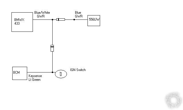
A diagram is worth a thousand words  :

remote start, 2004 grand prix -- posted image.

Soldering is fun!
amsanders843 
Member - Posts: 8
Member spacespace
Joined: November 17, 2011
Location: South Carolina, United States
Posted: November 24, 2011 at 3:14 AM / IP Logged  
Being that my car has a negative keysense, shouldnt the diode coming from the ignition switch be the other way around? And thanks a lot man for helping me out. I'm going to dig back into it tomorrow to see if this fixes the problem.
kreg357 
Platinum - Posts: 7,827
Platinum spaceThis member has made a donation to the12volt.com. Click here for more info.spaceThis member has been recognized as an authority in Electrical Theory. Click here for more info.spaceThis member has been recognized as an authority in Mobile Security and Convenience. Click here for more info.spacespace
Joined: January 30, 2009
Location: Pennsylvania, United States
Posted: November 24, 2011 at 4:10 AM / IP Logged  
The purpose of the diode is to prevent the (-) Keysense signal generated from inserting a key into the ignition cylinder from feeding back to the 556UW bypass module and turning it on during a normal key start-up.  The diode blocks this signal.  You only want the BMWX 433 GWR output to signal the 556UX and fool the vehicle into thinking a key is inserted during an actual remote start.
Soldering is fun!
amsanders843 
Member - Posts: 8
Member spacespace
Joined: November 17, 2011
Location: South Carolina, United States
Posted: November 24, 2011 at 4:38 AM / IP Logged  
oh okay. well isnt that just like wiring the keysense wire of the 556u to the car keysense wire? the 556u manual says doing this will achieve the same goal, canceling out the 556u when a key is inserted in the ign switch.
Page of 2

  Printable version Printable version Post ReplyPost New Topic
You cannot post new topics in this forum
You cannot reply to topics in this forum
You cannot delete your posts in this forum
You cannot edit your posts in this forum
You cannot create polls in this forum
You cannot vote in polls in this forum

  •  
Search the12volt.com
Follow the12volt.com Follow the12volt.com on Facebook
Monday, July 7, 2025 • Copyright © 1999-2025 the12volt.com, All Rights Reserved Privacy Policy & Use of Cookies
Disclaimer: *All information on this site ( the12volt.com ) is provided "as is" without any warranty of any kind, either expressed or implied, including but not limited to fitness for a particular use. Any user assumes the entire risk as to the accuracy and use of this information. Please verify all wire colors and diagrams before applying any information.

Secured by Sectigo
the12volt.com spacer
Support the12volt.com
Top
the12volt.com spacer