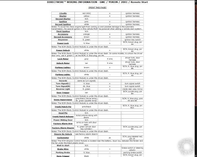
DIRECTWIRE WIRING INFORMATION - GMC / YUKON / 2001 / Remote Start
12volts
red (40A) + ignition harness
Starter
yellow + ignition harness
Second Starter
N/A
Ignition
pink + ignition harness
Second Ignition
white + ignition harness
Notes: To avoid the check engine light from coming on and possible damage to the automatic transmission, the second ignition in this vehicle MUST be powered when adding a remote start system.
Third Ignition
N/A
Accessory
orange + ignition harness
Second Accessory
brown + ignition harness
Keysense lt. green - ignition key switch
Power Lock
lt. blue + BCM, brown plug, pin A4
Notes: The BCM (Body Control Module) is under the driver dash.
Power Unlock
white + BCM, brown plug, pin A3
Notes: The BCM (Body Control Module) is under the driver dash. On some models, to unlock the driver door only, use lt. green (-) at the BCM, lt. blue plug, pin A4.
Lock Motor
gray 5 wire driver kick, door harness
Unlock Motor
tan 5 wire driver kick, door harness
Parking Lights+
brown + BCM, lt. blue plug, pin B6
Notes: The BCM (Body Control Module) is under the driver dash.
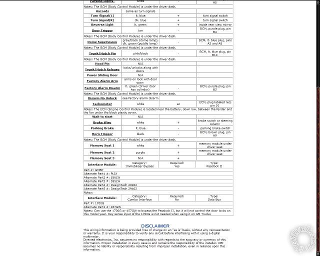
Parking Lights-
white - BCM, lt. blue plug, pin A5
Notes: The BCM (Body Control Module) is under the driver dash.
Hazards same as turn signals
Turn Signal(L) lt. blue + turn signal switch
Turn Signal(R) dk. blue + turn signal switch
Reverse Light lt. green + inside rear view mirror
Door Trigger
tan - BCM, purple plug, pin B4
Notes: The BCM (Body Control Module) is under the driver dash.
Dome Supervision
gray/black (dome lamp), dk. green (puddle lamp) - BCM, lt. blue plug, pins A3 and A8
Notes: The BCM (Body Control Module) is under the driver dash.
Trunk/Hatch Pin
pink/black - BCM, lt. blue plug, pin B10
Notes: The BCM (Body Control Module) is under the driver dash.
Hood Pin
N/A
Trunk/Hatch Release
locks/unlocks along with doors
Power Sliding Door N/A
Factory Alarm Arm
arms on lock with door open
Factory Alarm Disarm
lt. green (driver door key cylinder) -
BCM, purple plug, pin B3
Notes: The BCM (Body Control Module) is under the driver dash.
Disarm No Unlock see factory alarm disarm
Tachometer white ac ECM, plug labeled red, pin 10
Notes: The ECM (Engine Control Module) is located near the battery, down low, between the fender and the fan under the black plastic cover.
Wait to start N/A
Brake Wire white + brake switch or steering column
Parking Brake lt. blue - parking brake switch
Horn Trigger
black - BCM, brown plug, pin A9
Notes: The BCM (Body Control Module) is under the driver dash.
Memory Seat 1 white + memory module under driver seat
Memory Seat 2 purple + memory module under driver seat
Memory Seat 3 N/A +
Interface Module: Category:
Immobilizer Bypass Required:
Yes
Type:
Passlock II
Part #: GMBP
Alternate Part1 #: PLJX
Alternate Part2 #: 556LW
Alternate Part3 #: 555LW
Alternate Part4 #: DesignTech 20402
Alternate Part5 #: DesignTech 29402
Notes:
Interface Module: Category:
Combo Interface Required: No
Type: Data Bus
Part #: 1700G
Alternate Part1 #: 457GW
Notes: Can use the 1700G or 457GW to bypass the Passlock II, but it will not control the door locks on this model year. Key sense input of the 1700G is not needed when using it on GM Trucks
This wiring information is being provided free of charge on an "as is" basis, without any representation or warranty. It is your responsibility to verify any circuit before interfacing with it using a digital multimeter.
Directed electronics, Inc. assumes no responsibility with regards to the accuracy or currency of this information. Proper installation in every case is and remains the responsibility of the installer. DEI assumes no liability or responsibility resulting from improper installation, even in reliance upon this information.


 Topic Closed)


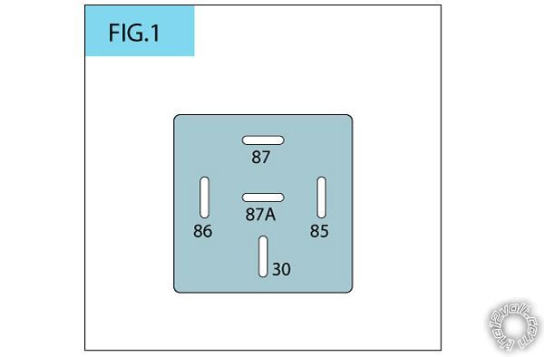 - Connect Pins 30 and 85 to the Red 12v constant wire of the car
- Connect Pin 87 to the Brown 2nd Accessory wire of the car
- Connect Pin 86 to the orange wire (H2/12) of the 18 pin Viper harness
- Connect Pins 30 and 85 to the Red 12v constant wire of the car
- Connect Pin 87 to the Brown 2nd Accessory wire of the car
- Connect Pin 86 to the orange wire (H2/12) of the 18 pin Viper harness Printable version


